


8
Regardless of whether you use one or two power supplies, when making a cooling system from a single TE module,
the maximum operating voltage for that
system
is usually no more than 75% of the rated Vmax of the TE module.
The 75% rule is based on the TE module being thermally connected to a “good” heat sink; system modeling should
be done to verify this rule is applicable though. If multiple TE modules are used in a series or series-parallel
combination, the Vmax of the system will be approximately 75% of the rated Vmax of each TE module multiplied
by the number of modules in series.
Operating Instructions
1.0
Setup
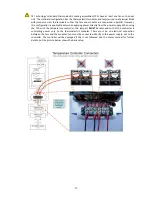
Portions of the temperature controller (the aluminum frame near the output transistors, for
example) could exceed 60 °C during normal operating conditions. Temperatures greater than 60 °C
can result in a hazard to the user. Use caution! Protect against accidental contact with hot
surfaces.
If the temperature controller is to be used under conditions such that its surface temperatures
could possibly exceed 60 °C, test the surface temperatures under the worst-case operating
conditions of maximum ambient temperature and highest output current and voltage. If any
portion of the temperature controller exceeds 60 °C place adequate guards around the
temperature controller to prevent contact with any hot surfaces.
NOTE: the maximum allowable ambient temperature for the controller is 50 °C. Furthermore, the
maximum allowable temperature of the controller base (underneath the transistor-mounting area)
is 90 °C. Furthermore, the controller might need additional heat sinking, depending on ambient
conditions and how much current is being drawn by the TE device.
Note: See “
Controller Wiring Diagram (One Power Supply Setup)”
or
“Controller Wiring Diagram (Two
Power Supplies Setup)”
for additional reference.
1.1
Set the position of jumper JP1.
•
To set the controller in cooling mode: JP1 is shorted (jumper is installed)
•
To set the controller in heating mode: JP1 is open (jumper is removed)
1.2
Attach the thermistor at an appropriate temperature-control location. Locating the thermistor at the cold
side of the TE device provides better control stability than locating it at the object, liquid, or air that is to be
cooled/heated. However, in doing so, there will be a temperature difference between the TE device and the
object, liquid, or air that is to be cooled/heated. The temperature set point can be adjusted to compensate
for this temperature difference if necessary.
NOTE: When possible, it is recommended that at least 50 mm of
the thermistor’s
wire be thermally
connected to the cold side of the TE device. This can be accomplished by placing aluminum tape over the
thermistor wires and adhering the wires and tape to the cold side of the cooler. If this is not done, the
thermistor wires will be at a different temperature than the cold side and they will add or remove heat in


