


15
3.0
Controller Tuning
Tuning of Proportional and Integral (PI) control requires knowing two parameters:
1.
The natural period of the system, and
2.
The bandwidth used to achieve this cycle.
This tuning method follows the Ziegler Nichols closed-loop tuning principals. Briefly, the controller will first be set
to a low gain (high Bandwidth) setting with no integral function (Integral rate = 0). Then, the gain is gradually
increased until the temperature approaches set point, and a small, sustained oscillation in temperature is
observed. The tuning parameters are then readjusted based on the time period of the temperature oscillation
(natural period) and the Bandwidth needed to cause this oscillation.
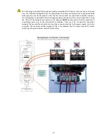
Improper tuning of this temperature controller can lead to excessive thermal cycling and/or
overheating of the thermoelectric device, either of which are known to reduce the lifetime of any
thermoelectric device. Care should be taken to prevent the temperature of the TE device from going
beyond the range specified by the device manufacturer. Care should also be taken so that any
thermal cycling of the TE device is a result of changes in the controller’s set
-point temperature and
not instability at a given set point due to improper selection of the tuning variables.
The potentiometers used on this controller are 25-turn devices. When the potentiometer has been adjusted to the
“
maximum clockwise
”
or
“maximum counter
clockwise
”
position, the adjustment pawl will ratchet on the screw-
driven gear, making a slight clicking sound.
3.1
Set the Integral Rate Potentiometer (R8) to zero by adjusting it to maximum counterclockwise.
3.2
Set the Proportional Bandwidth Potentiometer (R2) to 5 °C by adjusting it to maximum clockwise.
3.3
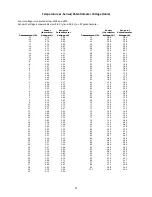
Set the desired control temperature by adjusting the Set Temperature Potentiometer (R7). See the
“
Temperature vs. Sensor/Potentiometer Voltage”
graphs and tables for the potentiometer voltage-set point
relationship.
3.4
Adjust the Proportional Bandwidth Potentiometer counterclockwise until a small, sustained temperature
oscillation is observed. (You can adjust in initial increments of 1 V, or 5 turns. Then, once an initial
oscillation is observed, adjust the potentiometer clockwise until the oscillations are barely detectable).
3.5
Record the number of turns (counterclockwise from the maximum clockwise position) on the Proportional
Bandwidth Potentiometer that are required to barely sustain this temperature oscillation.
_________________________ Turns
3.6
Calculate the bandwidth that corresponds to this potentiometer setting using the formula: Bandwidth = 5
°C
–
0.18 °C/turn x (number of turns recorded in section 3.5). (See Tuning Example below)
Bandwidth = _____________________ °C
3.7
The time that it takes to go from one peak temperature to the next peak temperature is the natural period.
Record the time of the natural period in minutes.
_________________________ Minutes


