


17
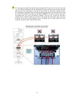
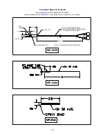
Controller Wiring Diagram (One Power Supply Setup)
Notes: R2 = Proportional bandwidth adjustment (0.5 to 5 °C), clockwise to increase
R7 = Set-point temperature adjustment (-20 to +100 °C), clockwise to increase
R8 = Integral rate adjustment (0 to 2.55 repeats per minute), clockwise to increase
All potentiometers have a 25-turn adjustment range.
WP1, WP2, WP3, WP4, WP5 and WP6 are 0.25 inch quick-connect terminals
When one or more external fans are used on the TE device, these should be wired directly to a fixed
voltage power supply for constant operation.
When connecting the controller to a TE Technology Thermoelectric Cooling Assembly (TCA) verify that
the electrical jumpers (shorts) located on the TCA terminal block are installed/removed per the TCA
operating manual before powering the controller.
THERMISTOR
TE DEVICE
(shown in cooling mode)
POTENTIOMETER
PIN IDENTIFICATION
DC
POWER SUPPLY
(+)
(-)
(+)
(-)
WP1
WP5
WP6
WP2
WP4
WP3
R8
R7
JP1
R2
1
2
3
=9 V, =26 V, 10 A maximum
FUSE
THERMOSTAT AND
OTHER PROTECTIVE
DEVICES


