background image

Help Hot Line (U.S. only): 1-800-530-9960

7-13

D-620616-0-20 Rev F

CONFIDENTIAL

Fusion Wideband Installation Procedures

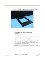
• The rack-mounting brackets on the Fusion Wideband Main Hub must be moved to 

the recessed mounting position (shown in Figure 7-2) to allow for the required 76 
mm (3 in.) rear clearance.

• The maximum weight the bracket can hold is 22.5 kg (50 lbs).

• The bracket is designed to accommodate a Fusion Wideband Main Hub (12 lbs.) or 

an Expansion Hub (14.5 lbs.).

• The wall mount bracket should be securely mounted to wall, using the four key slot 

mounting holes on the bracket.

Using the Wall Rack-Mounting Option

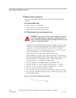
You can flip the rack mounting brackets, as shown in Figure 7-2, so the hub can be 
mounted 76 mm (3 in.) forward in the rack.

Figure 7-2

Bracket Detail For Wall Mount Rack (PN 4712)

To install the Hub to the wall-mounted rack:

1.

Attach the wall bracket (PN 4712) to wall the using #10 Pan Head wood screws, 
1-1/2” minimum length for mounting in wood studs or 3/4“thick plywood.

The bracket must be positioned so that the Hub will be in a horizontal position 
when it is installed. (Refer to Figure 7-2.)

NOTE:

If wall stud spacing of 16” is not available, TE recommends that 

3/4” plywood be pre-installed to the wall. You can then attach the bracket to 
the plywood using the wood screws.

2.

Remove both of the rack mounting brackets from the Hub.

3.

Reattach each of the rack mounting brackets to the recessed wall mount position.

Содержание InterReach Fusion ADCP-77-044

Страница 1: ...ADCP 77 044 Issue 5 June 2012 D 620616 0 20 Rev F InterReach Fusion Wideband Installation Operation and Reference Manual...

Страница 2: ...consequential or other similar damages This disclaimer of liability applies to all products publications and services during and after the warranty period This publication may be verified at any time...

Страница 3: ...itoring and Reporting 2 6 2 3 2 Using Alarm Contacts 2 6 2 4 System Connectivity 2 7 2 5 System Operation 2 8 2 6 System Specifications 2 9 2 6 1 RF End to End Performance 2 11 SECTION 3 Fusion Wideba...

Страница 4: ...nectors 5 5 5 2 1 50 Ohm Type N Connector 5 5 5 2 2 75 Ohm Type F Connector 5 5 5 3 RAU LED Indicators 5 5 5 4 Faults and Warnings 5 6 5 5 Remote Access Unit Specifications 5 7 SECTION 6 Designing a F...

Страница 5: ...ctor Requirements 7 2 7 1 3 Distance Requirements 7 3 7 2 Safety Precautions 7 3 7 2 1 Installation Guidelines 7 3 7 2 2 General Safety Precautions 7 4 7 2 3 Fiber Port Safety Precautions 7 4 7 3 Prep...

Страница 6: ...g an RAU 8 1 8 2 Replacing a Fusion Wideband Expansion Hub 8 3 8 3 Replacing a Fusion Wideband Main Hub 8 4 SECTION 9 Maintenance Troubleshooting and Technical Assistance 9 1 9 1 Service 9 1 9 2 Maint...

Страница 7: ...gs Status Tables for Fusion Fusion Wideband Fusion SingleStar A 1 C 1 Faults Reported by Main Hubs A 1 C 2 Faults Reported for System CPU A 5 C 3 Faults for Expansion Hubs A 6 C 4 Faults for RAUs A 9...

Страница 8: ...CONFIDENTIAL 6 InterReach Fusion Wideband Installation Operation and Reference Manual D 620616 0 20 Rev F...

Страница 9: ...2 Figure 3 2 Main Hub Block Diagram 3 3 Figure 3 3 Fusion Wideband Main Hub Front Panel 3 4 Figure 3 4 Fusion Wideband Main Hub Rear Panel 3 8 Figure 3 5 Preferences Check Boxes 3 12 Figure 4 1 Expan...

Страница 10: ...e 7 21 Internet Protocol TCP IP Properties Window 7 37 Figure 7 22 Local Area Connection Properties Window 7 38 Figure 7 23 Set Time and Date Window 7 39 Figure 7 24 AdminBrowser Configuration Window...

Страница 11: ...n Window 7 69 Figure 7 50 Connect Fusion Wideband Hub Window 7 70 Figure 7 51 Fusion Wideband Hub Properties Window 7 70 Figure 7 52 Modem Configuration Window 7 71 Figure 7 53 Fusion Wideband Hub Pro...

Страница 12: ...CONFIDENTIAL 4 InterReach Fusion Wideband Installation Operation and Reference Manual D 620616 0 20 Rev F...

Страница 13: ...MHz RF End to End Performance 2 14 Table 2 13 700 MHz Lower ABC RF End to End Performance 2 14 Table 2 14 700 MHz Upper C RF End to End Performance 2 15 Table 2 15 AWS RF End to End Performance 2 15...

Страница 14: ...Frequency Bands and the Value of the First Term in Equation 3 6 18 Table 6 17 Estimated Path Loss Slope for Different In Building Environments 6 18 Table 6 18 Approximate Radiated Distance from Antenn...

Страница 15: ...llation 7 31 Table 7 7 Troubleshooting RAU LEDs During Installation 7 36 Table 7 8 Alarm Types 7 56 Table 9 1 Troubleshooting Main Hub Port LEDs During Normal Operation 9 6 Table 9 2 Troubleshooting M...

Страница 16: ...CONFIDENTIAL 4 InterReach Fusion Wideband Installation Operation and Reference Manual D 620616 0 20 Rev F...

Страница 17: ...Software and Firmware Release and associated documentation access the TE Customer Portal at http www te com adc 1 2 Purpose and Scope This document describes the InterReach Fusion Wideband system Sec...

Страница 18: ...equirements safety precautions and checklists The installation procedures include guidelines for troubleshooting using the LEDs as you install the units Section 8 Replacing Fusion Wideband Components...

Страница 19: ...at indicates when a given action or omitted action can cause or contribute to a hazardous condition Damage to the equipment can occur WARNING This format indicates when a given action or omitted actio...

Страница 20: ...anual CONFIDENTIAL D 620616 0 20 Rev F 1 5 Related Publications AdminBrowser User Manual TE part number D 620607 0 20 FlexWave Focus Configuration Installation and Reference Manual TE part num ber 850...

Страница 21: ...es It provides high quality ubiquitous seamless access to the wireless network in larger buildings Fusion Wideband provides RF characteristics designed for large public and private facilities such as...

Страница 22: ...and of the 60 MHz Band Key System Features Multi Band supports two or more full band frequencies for spectrum growth Superior RF performance particularly in the areas of IP3 and noise figure High down...

Страница 23: ...ts to up to 4 Expansion Hubs except for the One Port Main Hub configuration that supports 1 Expansion Hub Converts RF signals to optical IF on the downlink optical IF to RF on the uplink Microprocesso...

Страница 24: ...ain Hub PN FSN W1 MH 1P and FSN W2 MH 1P configuration is a cost reduced version of the Fusion Wideband Main Hub and supports only one Expansion Hub up to 8 RAUs The Fusion Wideband One Port Main Hub...

Страница 25: ...ation for basic alarm monitoring Connection Methods The Main Hub s front panel RJ 45 port connects directly to a PC for local Ethernet access The Main Hub s front panel RS 232 serial port connects dir...

Страница 26: ...stall a new system or new components change sys tem parameters and query system status Figure 2 4 illustrates how the system reports its status to AdminBrowser Figure 2 4 System Monitoring and Reporti...

Страница 27: ...architecture of the Fusion Wideband system illustrated in Figure 2 5 provides excellent system scalability and reliability The system requires only one pair of fibers for eight antenna points This mak...

Страница 28: ...nverts the optical sig nals to electrical signals and sends them to RAUs up to eight using 75 Ohm CATV cable The RAU converts the IF signals to RF and sends them to passive antennas using 50 Ohm coaxi...

Страница 29: ...female CATV 75 Ohm One F female CATV 75 Ohm One N femaleb antenna 50 Ohm External Alarm Connector contact source One 9 pin D sub female One 9 pin D sub female ADMIN LAN Interface Connectors One RJ 45...

Страница 30: ...to 85 C 13 to 185 F Operating Humidity non condensing 5 to 95 5 to 95 Table 2 4 Frequency Bands Covered by Fusion Wideband RAUs Fusion Wideband RAU Part Number Fusion Wide band Band RF Passband Downli...

Страница 31: ...1755 2 45 MHz 700 700 MIMO Upper C FSN W2 7575 1 700 Upper C 746 757 776 787 1 sub band 1A 11 MHz 700 Upper C 746 757 776 787 3 sub band 1B 11 MHz 700 700 MIMO Lower ABC FSN W2 7070 1 700 Lower ABC 72...

Страница 32: ...rformance Typical Parameter Downlink Uplink Average gain with 130 m RG 59 at 25 C 77 F dB 15 15 Ripple with 130 m RG 59 dB 4 5 5 Output IP3 dBm 38 Input IP3 dBm 5 Output 1 dB Compression Point dBm 26...

Страница 33: ...Us dB 17 Noise Figure 1 MH 4 EH 32 RAUs dB 23 Table 2 9 AWS RF End to End Performance Typical Parameter Downlink Uplink Average gain with 130 m RG 59 at 25 C 77 F dB 15 15 Ripple with 130 m RG 59 dB 3...

Страница 34: ...RAUs dB 23 Table 2 12 1900 MHz RF End to End Performance Typical Parameter Downlink Uplink Average gain with 130 m RG 59 at 25 C 77 F dB 15 15 Ripple with 130 m RG 59 dB 3 5 4 Output IP3 dBm 38 Input...

Страница 35: ...AUs dB 26 Table 2 15 AWS RF End to End Performance Typical Parameter Downlink Uplink Average gain with 130 m RG 59 at 25 C 77 F dB 15 15 Ripple with 130 m RG 59 dB 3 5 4 Output IP3 dBm 38 Input IP3 dB...

Страница 36: ...dBm 38 Input IP3 dBm 5 Output 1 dB Compression Point dBm 26 Noise Figure 1 MH 1 EH 8 RAUs dB 17 Noise Figure 1 MH 4 EH 32 RAUs dB 23 Typical Parameter Downlink Uplink Average gain with 130 m RG 59 at...

Страница 37: ...ibutes up to three indi vidual Band 1 2 and 3 downlink RF signals from a base station repeater or Flex Wave Focus system to up to four Expansion Hubs which in turn distribute the signals to up to 32 R...

Страница 38: ...epeater or FlexWave Focus system using 50 Ohm coaxial cable It converts the signals to IF then to optical and sends them to up to four Expansion Hubs using fiber optic cable The Main Hub also sends OA...

Страница 39: ...Help Hot Line U S only 1 800 530 9960 3 3 D 620616 0 20 Rev F CONFIDENTIAL Fusion Wideband Main Hub Overview Figure 3 2 Main Hub Block Diagram CAL Tone...

Страница 40: ...r port for port link status and downstream unit status 3 One set of unit status LEDs One LED for unit power status labeled POWER One LED for unit status labeled MAIN HUB STATUS 4 One 9 pin D sub male...

Страница 41: ...onnectors are used throughout the fiber network includ ing fiber distribution panels 3 2 2 Communications RS 232 Serial Connector Remote Monitoring Use a standard serial cable to connect a modem to th...

Страница 42: ...lems within the system the LEDs may provide additional infor mation that is not available using AdminBrowser Unit Status LEDs The Main Hub has one pair of status LEDs labeled POWER and STATUS which ca...

Страница 43: ...ta is built power up system test is executed and all units have their current status updated Should the MH status LED blink red green after initial power up either the System CPU has rebooted or a com...

Страница 44: ...male connector for contact alarm monitoring labeled ALARMS 5 Ground lug for connecting unit to frame ground labeled GROUND 3 3 1 Fusion Wideband Main Hub Rear Panel Connectors 3 3 1 1 9 pin D sub Conn...

Страница 45: ...receives downlink RF signals from a repeater local base station or FlexWave Focus system The UPLINK connector transmits uplink RF signals to a repeater local base sta tion or FlexWave Focus system CA...

Страница 46: ...e Connector 1 RJ 45 female 1 9 pin D sub male for optional modem Fiber Connectors 4 Pair SC APCb b It is critical to system performance that only SC APC fiber connectors are used throughout the fiber...

Страница 47: ...warning or status message Faults are service impacting Warnings indicate a possible service impact Status and informational messages are generally not service impacting The Fusion Wideband Main Hub pe...

Страница 48: ...AdminBrowser select Alarms Set Alarm Preference and select the desired choice After you click OK AdminBrowser refreshes and updates the tree view according to the new setting NOTE The setting is stri...

Страница 49: ...n Hub Figure 4 1 Expansion Hub in a Fusion Wideband System Fusion Wideband Expansion Hub Fusion Wideband Main Hub RAU Downlink Path The Expansion Hub receives downlink Band 1 2 and 3 optical signals f...

Страница 50: ...Expansion Hub Overview 4 2 InterReach Fusion Wideband Installation Operation and Reference Manual CONFIDENTIAL D 620616 0 20 Rev F Figure 4 2 Expansion Hub Block Diagram...

Страница 51: ...unit status labeled E HUB STATUS 4 One set of fiber connection status LEDs One LED for fiber downlink status labeled DL STATUS One LED for fiber uplink status labeled UL STATUS 5 One fiber optic port...

Страница 52: ...test purposes DO NOT CON NECT ANYTHING TO IT Local Monitoring Use a crossover Ethernet cable PN 4069 ADB to directly connect a laptop or PC to the RJ 45 female connector for local monitoring or config...

Страница 53: ...us and DL UL status LEDs can be in one of the states shown in Table 4 1 These LEDs can be steady green steady red off Table 4 1 Expansion Hub Unit Status and DL UL Status LED States LED State Indicate...

Страница 54: ...ially green then red after 90 seconds it means that there is no communication with the Main Hub If red on power up replace the Expansion Hub No optical faults have been detected but no valid message w...

Страница 55: ...off steady green steady red flashing red 60 pulses per minute PPM Table 4 2 Fusion Wideband Expansion Hub Port LED States LED State Indicates Off The RAU is not connected Green The RAU is connected N...

Страница 56: ...ound labeled GROUND Table 4 3 9 pin D sub Pin Connector Functions This interface can monitor three single external alarm contacts Alarm Sense Input 1 This interface monitors the output contact closure...

Страница 57: ...ot service impacting 4 4 Faults Warnings and Status Messages Both fault and warning conditions of the Expansion Hub and attached RAUs are reported to the Main Hub Only faults are indicated by LEDs For...

Страница 58: ...ant that you use only recommended CATV 75 Ohm cable with quality F connectors 8 F female CATV 75 Ohm Fiber Connectorsb b It is critical to system performance that only SC APC fiber connectors are used...

Страница 59: ...lts and Warnings 5 6 Section 5 5 Remote Access Unit Specifications 5 7 5 1 RAU Overview The Remote Access Unit RAU is an active transceiver that connects to an Expan sion Hub using industry standard C...

Страница 60: ...ends them to a passive RF antenna using 50 Ohm coaxial cable Also the RAU receives con figuration information from the Fusion Wideband Hub using the 75 Ohm CATV cable Uplink Path The RAU receives upli...

Страница 61: ...1 60 MHz 1800 1805 1880 1710 1785 2 75 MHz 2100 High Power single band RAU FSN W1 21HP 1 2100 2110 2170 1920 1980 1 60 MHz 1900 AWS FSN W1 1921 1 1900 A F 1930 1990 1850 1910 1 60 MHz AWS 2110 2155 17...

Страница 62: ...2500 2570 1 70 MHz 2600 2620 2690 2500 2570 2 70 MHz Table 5 2 System Gain Loss Relative to CATV Cable Length Cable Type Comm Scope Part Number Plenum Rated Solid Copper Conductor Copper Clad Conduct...

Страница 63: ...75 Ohm cable Use RG 59 6 or 11 solid copper center conductor cables NOTE For system performance it is important that you use only low loss solid copper center conductor CATV cable with quality F conn...

Страница 64: ...Green Green The RAU is powered and is not indicating a fault condition Communication with the Fusion Wideband Hub is normal however the system test may need to be performed or a warning con dition may...

Страница 65: ...tions Specification Description Dimensions H W D 54 mm 286 mm 281 mm 2 13 in 11 25 in 11 13 in Weight 2 1 kg 4 6 lb Operating Temperature 25 to 45 C 13 to 113 F Non operating Temperature 25 to 85 C 13...

Страница 66: ...Remote Access Unit Specifications 5 8 InterReach Fusion Wideband Installation Operation and Reference Manual CONFIDENTIAL D 620616 0 20 Rev F...

Страница 67: ...a Base Station 6 37 6 1 Overview Designing a Fusion Wideband solution is a matter of determining coverage and capacity needs This requires the following steps 1 Determine the wireless service provide...

Страница 68: ...in building environment Refer to Section 6 5 Estimating RF Coverage on page 6 16 Determine which areas of the building require coverage entire building public areas parking levels and so on Obtain fl...

Страница 69: ...k signal level and an associated confidence factor when specifying coverage requirements These two fig ures of merit are a function of wireless handset sensitivity and margins for fading and body loss...

Страница 70: ...e number of RF carrier increases the maximum power per carrier decreases If these levels are exceeded signal quality will be degraded and or regulator requirements will be violated The maximum input p...

Страница 71: ...55022 emissions requirements Table 6 2 700 MHz Upper C Power per Carrier No of Carriers Power per Carrier dBm LTE 1 14 0 2 11 0 3 9 0 4 8 0 5 7 0 Note Operation at or above these output power levels m...

Страница 72: ...FCC Part 15 and EN55022 emissions require ments Table 6 4 700 MHz Lower ABC Power per Carrier Number of Carriers Power per Carrier dBm WCDMA LTE 1 18 0 18 0 2 15 0 15 0 3 13 0 13 0 4 12 0 12 0 5 11 0...

Страница 73: ...8 0 4 5 6 0 6 0 6 0 11 7 5 4 0 12 7 0 3 5 13 7 0 3 0 14 6 5 3 0 15 6 0 2 5 16 6 0 2 0 Note Operation at or above these output power levels may prevent Fusion Wideband from meeting RF performance spec...

Страница 74: ...E 1 16 5 16 5 18 0 18 0 18 0 2 13 5 13 5 15 0 15 0 15 0 3 11 5 11 5 13 0 13 0 13 0 4 10 0 10 0 12 0 12 0 12 0 5 9 0 9 0 11 0 11 0 11 0 6 8 5 8 5 10 0 7 8 0 8 0 9 5 8 7 5 7 5 9 0 9 7 0 7 0 10 6 5 6 5 1...

Страница 75: ...r dBm GSM EDGE 1 16 5 16 5 2 14 5 14 5 3 12 5 12 5 4 11 5 11 5 5 10 5 10 5 6 9 5 9 5 7 9 0 9 0 8 8 5 8 0 9 8 0 7 5 10 7 5 7 0 11 7 0 6 5 12 6 5 6 0 13 6 5 6 0 14 6 0 5 5 15 5 5 5 0 16 5 5 5 0 20 4 5 4...

Страница 76: ...16 5 16 5 18 0 18 0 18 0 2 15 5 15 5 15 0 15 0 15 0 3 13 5 13 5 13 0 13 0 13 0 4 12 0 12 0 12 0 12 0 12 0 5 11 0 10 5 11 0 11 0 11 0 6 10 5 9 5 10 0 7 10 0 9 0 9 5 8 9 0 8 0 9 0 9 8 5 7 5 10 8 0 7 0 1...

Страница 77: ...8 0 18 0 2 15 5 15 5 15 0 15 0 15 0 3 13 5 13 5 13 0 13 0 13 0 4 12 0 12 0 12 0 12 0 12 0 5 11 0 10 5 11 0 11 0 11 0 6 10 5 9 5 10 0 7 10 0 9 0 9 5 8 9 0 8 0 9 0 9 8 5 7 5 10 8 0 7 0 11 7 5 6 5 12 7 0...

Страница 78: ...ns or FCC Part 15 and EN55022 emissions requirements Table 6 11 UMTS Power per Carrier No of Carriers Power per Carrier dBm WCDMA 1 22 0 2 18 0 3 15 0 4 13 5 5 12 0 6 11 0 7 10 0 Note Measurements tak...

Страница 79: ...ased on capacity growth forecasts There are two options for dealing with this scenario 1 Design the initial coverage with a maximum power per carrier for four RF carri ers This will likely result in a...

Страница 80: ...attenuated by 0 or 10 dB using AdminBrowser The recommended maximum lengths of CATV cable are as follows For RG 59 cable 130 meters for CommScope PN 2065V For RG 6 cable 140 meters for CommScope PN 22...

Страница 81: ...able to ensure successful operation Table 6 13 System Gain Loss Relative to CATV Cable Length Cable Type Comm Scope Part Number Plenum Rated Solid Copper Conductor Copper Clad Conductor Zero loss RF M...

Страница 82: ...igure 6 1 Determining APL between the Antenna and the Wireless Device APL P Lcoax G RSSI 1 where APL the maximum allowable path loss in dB P the power per carrier transmitted by the RAU in dBm Lcoax t...

Страница 83: ...that depends on partition material and geome tries inside the building and is accounted for by the log normal fade margin used in the downlink RSSI design goal calculation As a reference Table 6 15 p...

Страница 84: ...in Equation 3 Frequency Band MHz Mid Band Frequency MHz 20log10 4 f c Uplink Downlink 800 MHz SMR 806 824 851 869 838 30 9 850 MHz Cellular 824 849 869 894 859 31 1 1800 MHz DCS 1710 1785 1805 1880 17...

Страница 85: ...ent medium to high amount of RF obstructions Office Space with approx imately 50 cubicles and 50 hard walled offices 37 6 34 8 Dense Environment large amount of RF obstructions Hospital Office Space w...

Страница 86: ...ironment 75 246 Moderately Open Environment 58 191 Mildly Dense Environment 50 166 Moderately Dense Environment 42 137 Dense Environment 30 100 Table 6 21 Approximate Radiated Distance from Antenna fo...

Страница 87: ...nt 28 93 Table 6 23 Approximate Radiated Distance from Antenna for 1 7 2 1 GHz AWS Applications Facility Distance from Antenna Meters Feet Open Environment 67 220 Moderately Open Environment 52 172 Mi...

Страница 88: ...example a design goal of 85 dBm is used Suppose 3 dBi omni directional antennas are used in the design Then the maximum RF propa gation loss should be no more than 94 5 dB 6 5 dBm 3 dBi 85 dBm over 95...

Страница 89: ...cable distances are as recommended If the dis tances differ use the tables in Section 6 4 System Gain on page 6 14 to deter mine system gains or losses The path loss may need to be recalculated to ass...

Страница 90: ...stomer portal at http www te com adc for the on line Link Budget Tool 6 6 1 Elements of a Link Budget for Narrowband Standards The link budget represents a typical calculation that might be used to de...

Страница 91: ...ertain C I ratio Fusion Wideband Noise Figure This is Fusion Wideband s uplink noise figure which varies depending on the number of Expansion Hubs and RAUs and the frequency band Fusion Wideband s upl...

Страница 92: ...ts of shadowing are partially accounted for since it is characterized by relatively slow changes in power level Body Loss This accounts for RF attenuation caused by the user s head and body Minimum Re...

Страница 93: ...nsmitter a BTS transmit power per carrier dBm 33 b Attenuation between BTS and Fusion Wideband dB 23 c Power into Fusion Wideband dBm 10 d Fusion Wideband gain dB 0 e Antenna gain dBi 3 f Radiated pow...

Страница 94: ...b Attenuation between BTS and Fusion Wideband dB 10 c Fusion Wideband gain dB 0 d Fusion Wideband noise figure dB 1 4 32 22 e System noise figure dB 22 6 f Thermal noise dBm 30 kHz 129 g Required C I...

Страница 95: ...nels Table 6 28 shows an example This table assumes that there are 15 active traffic channels operating with 50 voice activity so that the total power adds up to 100 Notice that the pilot and sync cha...

Страница 96: ...he difference in fiber lengths to Expansion Hubs with overlapping coverage areas produces at least 1 chip 0 8 S delay of one path relative to the other then the multipaths signals can be resolved and...

Страница 97: ...instance using different lengths of cable then the required Eb No is lower and the mul tipath fade margin in the link budget can be reduced in some cases If the receiver noise figure is NF dB then the...

Страница 98: ...m 9 0 f Composite power into Fusion Wideband dBm 16 0 g Fusion Wideband gain dB 0 0 h Antenna gain dBi 3 0 i Radiated power per channel dBm 12 0 j Composite radiated power dBm 19 0 Airlink k Handoff g...

Страница 99: ...6 0 20 Rev F CONFIDENTIAL Link Budget Analysis b and c see notes in Table 6 29 regarding power per carrier downlink e a d f c d i e g h j f g h p k l m n o s q r v s t u w j p v x j downlink m uplink...

Страница 100: ...e figure dB 33 3 f Thermal noise dBm Hz 174 0 g Noise rise 75 loading dB 6 0 h Receiver interference density dBm Hz 134 6 i Information rate dB Hz 41 6 j Required Eb No lo 5 0 k Handoff gain dB 0 0 l...

Страница 101: ...output power requirements for a bi directional amplifier repeater Ensuring that noise radiated on the uplink from the in building system does not cause the outdoor base station to become desensitized...

Страница 102: ...ned measurements are taken with these connectors in place The Fusion Wideband optical power budget for both multi mode and sin gle mode fiber cable is 3 0 dB optical The maximum loss through the fiber...

Страница 103: ...limited by Fusion Wideband not by the attenuator However some base stations trigger alarms if the noise or signal levels are too high In this case the attenuation must be large enough to prevent this...

Страница 104: ...of each band s uplink RF input and if that level exceeds 30 dBm an RF attenuator is activated The level of attenuation is equal to the amount that the input exceeds 30 dBm The fol lowing sequence desc...

Страница 105: ...ed and mobile phones in the area of that RAU band will have to trans mit at a higher power This would increase interference to the outdoor network from such mobiles Uplink Attenuation The uplink atten...

Страница 106: ...ingle or multiple wireless devices in very close proximity to the RAU band Compression causes signal degradation and ultimately dropped calls and data errors and should be prevented Two settings are a...

Страница 107: ...n 7 6 Interfacing the Fusion Wideband Main Hub to an RF Source 7 46 Section 7 7 Connecting Contact Alarms to a Fusion Wideband System 7 56 Section 7 8 Alarm Monitoring Connectivity Options 7 63 7 1 In...

Страница 108: ...bution panels These cables are widely used industry standards for the cable TV industry The regu lations and guidelines for Fusion Wideband cable installation are identical to those specified by the T...

Страница 109: ...user serviceable parts inside the components Table 7 1 Distance Requirements Equipment Combination Cable Type Cable Length Additional Information Repeater BTS to Fusion Wideband Main Hub Coaxial N ma...

Страница 110: ...S only 1 408 952 2400 International When you connect the fiber optic cable clean all optical fiber SC APC connectors according to the cable manufacturer s instructions When you connect a radiating an...

Страница 111: ...d contact with broken fibers they are sharp and can pierce the skin Report any broken fiber cables and have them replaced Cleaning Be sure the connectors are clean and free of dust or oils Use only ap...

Страница 112: ...ent clearly marked System Design Used to verify frequency bands after installation Power available Fusion Wideband Main Hub AC Fusion Wideband Expansion Hub AC To RAU DC Fusion Wideband Main Hub DC Fu...

Страница 113: ...PN 4024 3 For contact alarm monitoring of fault and warning alarms Used to feed the alarms from multiple Fusion Wideband Main Hubs into a BTS or FlexWave Focus N C Operation Cabling Coaxial repeater...

Страница 114: ...r a remote connection Distances Fusion Wideband Main Hub is within 3 6m 10 20 ft of connecting repeater BTS Flex Wave If longer distance determine the loss of the cable used for this connection and ad...

Страница 115: ...ge 7 11 Cable management Cable manager PN 4759 Tie wrap bar PN 4757 Splice trays Pigtails with SC APC connectors 3 m 10 ft Multi mode fiber SC APC pigtail PN 4012SCAPC 10 Single mode fiber SC APC pigt...

Страница 116: ...Main Hub Directly to the Wall 7 14 Connecting the Fiber Cables to the Main Hub 7 15 Making Power Connections 7 18 Powering On the Main Hub 7 23 Installing Expansion Hubs 7 25 Installing an Expansion H...

Страница 117: ...S 7 54 Connecting Contact Alarms to a Fusion Wideband System 7 56 Alarm Source 7 57 Alarm Sense 7 60 Alarm Cables 7 62 Alarm Monitoring Connectivity Options 7 63 Direct Connection 7 63 Modem Connectio...

Страница 118: ...s threads To install the Hub in a rack 1 Insert spring nuts into rack where needed or use existing threaded holes 2 Place the Hub into the rack from the front 3 Align the flange holes with the spring...

Страница 119: ...You can flip the rack mounting brackets as shown in Figure 7 2 so the hub can be mounted 76 mm 3 in forward in the rack Figure 7 2 Bracket Detail For Wall Mount Rack PN 4712 To install the Hub to the...

Страница 120: ...b directly to the wall 1 Pre install 3 4 plywood to the wall 2 Mount both of the rack mounting brackets using 10 32 machine screws refer to illustration Figure 7 4 3 Attach the Hub to the wall so the...

Страница 121: ...irm that the total optical loss of fiber cable from the Main Hub through distribution panels and patch cords to the Expansion Hub does not exceed the optical budget Make sure the fiber cable s connect...

Страница 122: ...slowly insert the tip into the connector 3 Gently twist the swab to clean the port 4 Insert a dry swab into the port to dry it Additionally you can use compressed air after the alcohol has completely...

Страница 123: ...s If the fiber jumper is labeled with 1 or 2 1 Connect 1s to UPLINK ports on the Main Hub 2 Connect 2s to DOWNLINK ports on the Main Hub 3 Record which cable number and port number you connected to UP...

Страница 124: ...ns Use only UL listed AWM wire rated 600V and 90 degrees C If wires larger than 6AWG are needed from the DC power source follow local codes for reducing the wire size at hub connection point Follow lo...

Страница 125: ...of the DC power source installed at your site Color code standards for DC wiring do not exist To ensure that the correct polarity is connected to the hubs confirm the connection of the power cables to...

Страница 126: ...h Fusion Wideband Installation Operation and Reference Manual CONFIDENTIAL D 620616 0 20 Rev F 8 Install the clear protective cover with the pan head screws as shown in Figure 7 8 Figure 7 8 Pan Head...

Страница 127: ...viously explained WARNING Before connecting power wires be sure the power source is shut off and the power switch of the hubs are in the OFF position Connect the ground wires before connecting the pow...

Страница 128: ...on Operation and Reference Manual CONFIDENTIAL D 620616 0 20 Rev F Figure 7 11 Grounding Wire Connection Figure 7 12 Power Wires and Studs 3 Install the finish wires using the proper polarity and secu...

Страница 129: ...ch the clear protective cover and secure it with the two 8 32 pan head screws supplied with the Hub as shown in Figure 7 14 Figure 7 14 DC Illustration Detail Powering On the Main Hub 1 Connect the AC...

Страница 130: ...r fault do not use the port Off 2 Main Hub power is On with Expansion Hubs con nected and powered on PORT Off If the port LEDs do not illuminate check the fiber uplink for excessive optical loss If Ex...

Страница 131: ...AUTION Install Expansion Hubs in indoor locations only Installing an Expansion Hub in a Rack Consideration The Expansion Hub is shipped with 10 32 mounting screws Another common rack thread is 12 24 C...

Страница 132: ...22 5 kg 50 lbs Figure 7 16 Bracket Detail For Wall Mount Rack PN 4712 To install the hub in a wall mounted rack 1 Attach the equipment rack to the wall using the screws that are provided The rack mus...

Страница 133: ...tall the Hub directly to the wall 1 Pre install 3 4 plywood to the wall 2 Mount both of the rack mounting brackets using 10 32 machine screws refer to illustration Figure 7 17 3 Attach the Hub to the...

Страница 134: ...to the Wall NOTE Leave the dust caps on the fiber ports until you are ready to connect the fiber optic cables Installing an Optional Cable Manager in the Rack Using the screws provided fasten the cab...

Страница 135: ...budget Make sure the fiber cable s connectors are SC APC angle polished Using any other connector type will result in degraded system performance and may damage the equipment You can use an SC APC pi...

Страница 136: ...S and E HUB STATUS LEDs do not turn green green check the Main Hub LEDs See page 7 24 item 2 in Table 7 5 Connecting the 75 Ohm CATV Cables Considerations Verify that the cable has been tested and the...

Страница 137: ...ensor fault do not use the port UL STATUS Red after power up blink Replace the Expansion Hub The Expansion Hub laser is not operational no uplink between the Expansion Hub and Main Hub UL STATUS Red C...

Страница 138: ...ers This method of mounting must securely hold a minimum of 7 lbs load Attach the RAU securely to a stationary object that is a wall pole or ceiling tile For proper ventilation Keep at least 76 mm 3 i...

Страница 139: ...MHz Tx 851 869 Rx 806 824 and Tx 935 941 Rx 896 902 while the Cellular A and B carriers share a single 850 MHz block Tx 869 894 Rx 824 849 The combination of these frequency bands 800 900 MHz iDEN an...

Страница 140: ...r Downlink and 900 MHz iDEN Uplink A 2 MHz frequency gap 896 894 MHz separates the 850 Cellular downlink and 900 iDEN uplink frequency bands Because of this narrow spacing 850 Cellular downlink interm...

Страница 141: ...the LEDs will blink for two seconds as a visual check that they are functioning After the two second test The LINK LED should be green indicating it is receiving power and communi cations from the Fu...

Страница 142: ...ser 1 Connect the AC power cord to the Hub Make sure the Hub is grounded through the ground lug on the AC power and the frame ground lug as required The warranty does not cover damage caused when an u...

Страница 143: ...nections The LEDs blink for 20 seconds as a visual check that they are functioning 5 Connect the cross over Ethernet cable to the PC laptop and then to the RJ 45 100 BASE T port on the Hub s front pan...

Страница 144: ...ress 5 Change the IP address to 192 168 0 101 6 Change the Subnet mask to 255 255 255 0 7 Change the Default gateway to 192 168 0 1 8 Click OK twice You may be asked if you want to reboot your compute...

Страница 145: ...dminBrowser appears log in using the default user ID operator and the default password password 4 Click System Configuration and then click Set Date Time A window similar to Figure 7 23 appears Figure...

Страница 146: ...run on power up when this box is checked even if a scheduled system is not enabled Enter values to schedule the date and time of the next system test Enter values to specify the recurrence of the test...

Страница 147: ...to specify the Uplink and Downlink gain for each band You can set system gain within the specified range in 1 dB increments Use the pull down to set the Uplink Automatic Level Control to either Singl...

Страница 148: ...nlink portion of the frame has elapsed Static Auto This mode causes the system to attempt to determine the cor rect switching time then enforce it The default is Static Auto Select the Band Synchroniz...

Страница 149: ...est is performed and finally the system tree is refreshed The icons should be Indicating that the band is correctly set on the Main Hub Indicating that the band is correctly set on the Expansion Hub I...

Страница 150: ...tion than fusion splices and are not recommended Using a fusion splicer involves fusing together two butted and cleaved ends of fiber The fusion splicer aligns the fibers and maintains alignment durin...

Страница 151: ...vlar or fiber glass strength members the extruded coating and the buffer coating in order to expose the bare fiber cladding plus core Ensure that sufficient slack is maintained in order to be able to...

Страница 152: ...deband system supports up to three RF sources one for Band 1 one for Band 2 and one for Band 3 This section explains how each Band can be con nected to its associated RF source Connecting a Fusion Wid...

Страница 153: ...and the Fusion Wideband Main Hub You can insert attenuators between the circulator or duplexer and Hub as needed 1 Connect an N male to N male coaxial cable to the duplex connector on the base station...

Страница 154: ...D 620616 0 20 Rev F Figure 7 28 Duplex Base Station to a Fusion Wideband Main Hub N male to N male Coaxial Cable Base Station Duplex T1 E1 to Mobile Switching Center Insert attenuator if needed N male...

Страница 155: ...ation is required You can use power combiner splitters to connect a Fusion Wideband Main Hub RF Band to multiple base stations as shown in Figure 7 29 Figure 7 29 Connecting a Fusion Wideband Main Hub...

Страница 156: ...er 5 Connect an N male to N male coaxial cable to the repeater 6 Connect the other end of the N male to N male coaxial cable to the circulator 1 connector 7 Connect an N male to N male coaxial cable t...

Страница 157: ...for maximum power specifications If the maximum composite power is too high attenuation is required Considerations 2 hybrid power combiner splitters one for uplink and one for downlink 2x1 for two Fu...

Страница 158: ...e hybrid power combiner splitter connected to the repeater BTS that matches the Band 1 frequency 3 Check Hub LEDs After connecting and powering on the Hub check all LEDs to ensure that the sys tem is...

Страница 159: ...ion Main Hub s Downlink Port for Band 1 Band 2 Band 3 UL1 UL2 UL3 DL1 DL2 DL3 AC Power Alarms N male to N male Coaxial Jumper Cable to Repeater or Base Station 2 x 1 Power Combiner Splitter N male to...

Страница 160: ...male coaxial jumper cable between each circulator and the repeater or base station 1 N male to N male coaxial jumper cable between each circulator and power com biner splitter Procedure 1 Connect the...

Страница 161: ...erly Make sure the Main Hub is grounded The warranty does not cover damage caused when an ungrounded Hub is powered on NOTE Use a 50 ohm terminator on any unused power combiner splitter ports Figure 7...

Страница 162: ...or when the end to end system test is not valid Alarm Sense refer to Section 7 7 2 on page 7 60 The Fusion Wideband Main Hub can monitor 3 external alarm contacts Each port can be configured for norma...

Страница 163: ...nd When you connect FlexWave Focus to the Fusion Wideband the Fusion Wideband Main Hub is the output of the alarms alarm source and Focus is the input alarm sense as shown in Figure 7 33 Focus support...

Страница 164: ...4 An interface cable is required between the daisy chain cable and the BTS Because BTS alarm interface pinouts and Fusion Wideband to BTS distances vary this cable is often custom and wired on site Re...

Страница 165: ...nfigured by the carrier for contact closure monitoring prior to connecting a Fusion Wideband Main Hub to it In order to take full advantage of Fusion Wideband s OA M capabilities you can use TE s Admi...

Страница 166: ...Wideband Main Hub is the input of the alarms alarm sense and the Unison is the output alarm source as shown in Figure 7 36 The input alarm sense needs to be set to normally closed NC Figure 7 36 Using...

Страница 167: ...Hot Line U S only 1 800 530 9960 7 61 D 620616 0 20 Rev F CONFIDENTIAL Connecting Contact Alarms to a Fusion Wideband System Figure 7 37 Alarm Sense Contacts 8 1 Diagnostic I External Equipment Contac...

Страница 168: ...n Unison FlexWave Focus Alarm Port DB 9 male to Fusion Unison FlexWave Focus Alarm Port DB 9 male to Fusion Unison FlexWave Focus Alarm Port DB 9 male to Fusion Unison FlexWave Focus Alarm Port Option...

Страница 169: ...0 BASE T Port Expander Connection 7 73 Section 7 8 4 POTS Line Sharing Switch Connection 7 74 Section 7 8 6 Ethernet LAN Connection 7 76 Section 7 8 7 SNMP Interface 7 77 7 8 1 Direct Connection In th...

Страница 170: ...he modem cable wiring informa tion Modem switch settings are as follows for US Robotics modem PC side 1 2 and 6 Up Fusion Wideband Hub side 2 and 6 Up 7 8 2 1 Setting Up Fusion Wideband Modem USR Mode...

Страница 171: ...on Wideband Hub 4 Make sure the modem type is None The Modem init string is for a USR modem The server address is the IP address of the MH 5 Click Setup Connection 7 8 2 2 Setting Up a PC Modem Using...

Страница 172: ...on Operation and Reference Manual CONFIDENTIAL D 620616 0 20 Rev F Figure 7 42 Network Connections Window 2 Click Create a new connection The window shown in Figure 7 43 appears Figure 7 43 New Connec...

Страница 173: ...s Figure 7 44 New Connection Wizard Network Connection Type Window 4 Select Connect to the network at my workplace and click Next The window shown in Figure 7 45 appears Figure 7 45 New Connection Wiz...

Страница 174: ...L D 620616 0 20 Rev F Figure 7 46 New Connection Wizard Connection Name Window 6 Type a name for this connection and click Next The window shown in Figure 7 47 appears Figure 7 47 New Connection Wizar...

Страница 175: ...ing Connectivity Options Figure 7 48 New Connection Wizard Connection Availability Window 8 Select Anyone s use and click Next The window shown in Figure 7 49 appears Figure 7 49 New Connection Wizard...

Страница 176: ...Figure 7 50 Connect Fusion Wideband Hub Window 10 Type a password as indicated and click Properties The window shown in Figure 7 51 appears The default parameters are as follows User name ppp_user Pas...

Страница 177: ...m Configuration Window 12 Select the modem speed and other parameters for your modem as desired and click OK 13 Select the Security tab The window shown in Figure 7 53 appears Figure 7 53 Fusion Wideb...

Страница 178: ...ct Internet Protocol TCP IP as shown and click Properties The window shown in Figure 7 55 appears Figure 7 55 Internet Protocol Properties Window 16 Select Obtain an IP address automatically and Obtai...

Страница 179: ...the connection of multiple devices to a single PC with a 100 BASE T port Testing was performed with a Link sys 4 port switch Each Fusion Wideband MH must have a unique IP address Figure 7 56 OA M Con...

Страница 180: ...sharing switch you can connect two or more modems to a single tele phone line Figure 7 57 OA M Connection Using a POTS Line Sharing Switch Modem PSTN Line Sharing Switch Up to 4 modems per Switch Mode...

Страница 181: ...support Port Address Translation are best Modem PSTN Line Sharing Switch Line Sharing Switch Line Sharing Switch Line Sharing Switch Line Sharing Switch M o d e m M o d e m M o d e m M o d e m M o d e...

Страница 182: ...8 6 Ethernet LAN Connection An Ethernet LAN connection can be used to communicate between the PC and Fusion Wideband Testing was performed with an Linksys 4 port LAN switch Figure 7 59 OA M Connection...

Страница 183: ...so be diagnosed with SNMP using a standard NMS net work management system optional SNMP resident software in Fusion Wideband provides SNMP interactions for Traps and Notification The Fusion Wideband S...

Страница 184: ...Alarm Monitoring Connectivity Options 7 78 InterReach Fusion Wideband Installation Operation and Reference Manual CONFIDENTIAL D 620616 0 20 Rev F...

Страница 185: ...Replacing an RAU 1 Using AdminBrowser log in and click SYSTEM INFORMATION 2 Click SHOW SYSTEM TREE select Fusion Wideband Main Hub and click GET SYS TEM INFORMATION All system settings for Hubs and R...

Страница 186: ...LEDs do not blink on power up replace the RAU 2 After several seconds both LEDs should change to green which indicates that the unit has been successfully replaced there is communication with the Hub...

Страница 187: ...se AdminBrowser to perform System Test in order to optimize performance During System Test the entire system is temporarily off line and no RF is being transmitted For a fully loaded system one Main H...

Страница 188: ...Hub with a new one 5 Connect the AC power cord and all cables 6 Connect the crossover Ethernet cable to the PC and then to the Main Hub s front panel 100Base T connector ADMIN LAN port 7 Start the st...

Страница 189: ...ted Checking the Main Hub s LEDs The LEDs should blink through a 5 second test on power up If the LEDs do not blink on power up replace the Main Hub If the LEDs do not illuminate at all make sure the...

Страница 190: ...Replacing a Fusion Wideband Main Hub 8 6 InterReach Fusion Wideband Installation Operation and Reference Manual CONFIDENTIAL D x620616 0 20 Rev F...

Страница 191: ...oubleshooting CATV 9 10 Section 9 5 Technical Assistance 9 10 9 1 Service There are no user serviceable parts in any of the Fusion Wideband components Faulty or failed components are fully replaceable...

Страница 192: ...Hold the can level during use If using isopropyl alcohol and foam tipped swab Use only 98 pure or more alcohol Procedure using compressed air 1 Remove the connector s dust cap 2 Spray the compressed...

Страница 193: ...problems All CATV 75 Ohm cable should be tested to TIA 570 B specifications The RAU will be damaged if the cable connector is not installed properly You must use AdminBrowser for troubleshooting the...

Страница 194: ...ND STATUSES This gives the present status of the system depending upon View Preferences for all components Faults usually impact service warnings may impact service status messages contain information...

Страница 195: ...Wide band Main Hub and work downstream Resolve all faults first and then check the warnings Take appropriate action to resolve the faults as indicated in the following tables In cases where there is...

Страница 196: ...Expansion Hub was previously connected but it is not currently con nected the Expansion Hub uplink cable disconnected AdminBrowser clears all disconnects caused by installation as part of the clean u...

Страница 197: ...one time If the fault remains replace the Main Hub Internal Main Hub fault Use AdminBrowser to check if the Main Hub is commanded Out of Service every Expansion Hub port status LED will be red as well...

Страница 198: ...on and has band pro grammed Use AdminBrowser s Clear All Disconnect Status command if you are permanently removing the RAU from service The Expansion Hub s port LEDs should change to Off Off The RAU...

Страница 199: ...ptical loss Power cycle Expansion Hub one time to check uplink laser No communications between the Main Hub and the Expansion Hub Uplink laser failure DL STATUS Red Check the downlink fiber for opti c...

Страница 200: ...ustomer service representative will contact you with assistance Company name End user name Type of system model number frequency Approximate time in service warranty sales order number Description of...

Страница 201: ...configuration and status information Use 75 Ohm type F connectors with captive centerpins Lengths RG 59 Minimum 0 meters 0 ft Maximum 130 meters 426 ft RG 6 Minimum 0 meters 0 ft Maximum 140 meters 45...

Страница 202: ...A 2 InterReach Fusion Wideband Installation Operation and Reference Manual CONFIDENTIAL D 620616 0 20 Rev F Figure A 1 CommScope 2065V for RG 59...

Страница 203: ...Help Hot Line U S only 1 800 530 9960 A 3 D 620616 0 20 Rev F CONFIDENTIAL Figure A 2 CommScope 2279V for RG 6...

Страница 204: ...d Installation Operation and Reference Manual CONFIDENTIAL D 620616 0 20 Rev F Figure A 3 CommScope 2293K for RG 11 NOTE TE requires solid copper center conductor CATV cable for proper DC voltage to t...

Страница 205: ...F connector FP C55A Crimp Tool TC 1 Crimp Die TCD 35CA Cable Strip preparation tool TS100E CommScope cable part number 2293V Canare part number F connector FP C71A Crimp Tool TC 1 Crimp Die TCD 7CA C...

Страница 206: ...ation and status information Use industry standard 62 5 m 125 m MMF or Corning SMF 28 fiber or equiva lent SC APC angle polished connectors are required throughout the fiber network port to port inclu...

Страница 207: ...l loss maximum A 3 Coaxial Cable Connects a Fusion Wideband Hub to a repeater or base station N type connectors Connects an RAU to a passive antenna N type connectors A 4 Standard Modem Cable This cab...

Страница 208: ...Browser with a Fusion Wideband Hub A cable is included with the Fusion Wideband Hub The pinouts for this cable are illustrated in Figure A 2 Figure A 2 Wiring Map for TCP IP Cable 1 2 3 4 5 6 7 8 Brow...

Страница 209: ...ram of its wiring Figure A 3 DB 9 Female to DB 9 Female Null Modem Cable Diagram Table A 2 DB 9 Female to DB 9 Female Null Modem Cable Pinout From Signal To Signal P1 4 DTR P2 6 P2 1 DSR DCD P1 6 DSR...

Страница 210: ...A 10 InterReach Fusion Wideband Installation Operation and Reference Manual CONFIDENTIAL D 620616 0 20 Rev F...

Страница 211: ...to IEC 60950 3rd Edition and IEC 60950 1 1st Edition with all national deviations EMC FCC part 15 class A Radio FCC part 27 800 SMR iDEN Products Safety UL CSA CB Scheme certificate to IEC 60950 3rd...

Страница 212: ...cheme certificate to IEC 60950 3rd Edition and IEC 60950 1 1st Edition with all national deviations EMC EN 301 489 23 V1 2 1 Radio EN 301 908 11 V2 3 1 1700 2100 AWS Products Safety UL CSA CB Scheme c...

Страница 213: ...cause harm ful interference and 2 this device must accept any interference received including interference that may cause undesired operation NOTE This equipment has been tested and found to comply wi...

Страница 214: ...evaluation is performed by taking the maximum power output of the equipment the gain of the antenna to be used and distance from the antenna refer enced in FCC OET Bulletin 65 Evaluation Compliance w...

Страница 215: ...S only 1 800 530 9960 B 5 D 620616 0 20 Rev F CONFIDENTIAL Using S PG 4 R2 S 224 4x3 14 x 122 2 0 001 mW cm2 Also assuming a minimum distance of 20 cm according to FCC regulations S 224 4 x 3 14 x 20...

Страница 216: ...B 6 InterReach Fusion Wideband Installation Operation and Reference Manual CONFIDENTIAL D 620616 0 20 Rev F...

Страница 217: ...les contain messages for all versions of firmware but all messages are not displayed by a given firmware version C 1 Faults Reported by Main Hubs Faults indicate service impacting conditions and shoul...

Страница 218: ...sists replace the Hub MF14 Hardware failure 54 VDC 54 VDC power supply is out of range replace the Hub MF15 Hardware failure RF VDC Power Loss of DC power to RF circuits replace the Hub MF16 Self Lock...

Страница 219: ...okay try selecting a fixed number of symbols MF46 Problem detected in the Hub Contact TE Support for more information MF47 Problem detected in the Hub Contact TE Support for more information MF48 Pro...

Страница 220: ...TE Support for more information MF162 Problem detected in the Hub Contact TE Support for more information MF163 Problem detected in the Hub Contact TE Support for more information MF164 Problem detec...

Страница 221: ...t executing System CPU rebooted SF16 Problem detected in the System CPU Contact TE Support for more information SF17 Problem detected in the System CPU Contact TE Support for more information SF18 Pro...

Страница 222: ...eplace the Hub EF11 Hardware failure 54 VDC 54 VDC power supply is out of range replace the Hub EF12 Problem detected in the EH Contact TE Support for more information EF13 Band not programmed Cycle p...

Страница 223: ...rt for more information EF38 Problem detected in the EH Contact TE Support for more information EF39 Problem detected in the EH Contact TE Support for more information EF40 Problem detected in the EH...

Страница 224: ...an RAU problem ET150 Port 6 Cable Fault Possible electrical short in the coaxial cable or an RAU problem ET151 Port 7 Cable Fault Possible electrical short in the coaxial cable or an RAU problem ET15...

Страница 225: ...sists replace the RAU RF15 Hardware Failure UL PLL Band 2 Cycle power once If the fault persists replace the RAU RF16 Hardware Failure UL PLL Band 3 Cycle power once If the fault persists replace the...

Страница 226: ...tallation Operation and Maintenance Manual Status Messages Status messages alert you to conditions that are important but generally do not impact service Status messages alert you to conditions that a...

Страница 227: ...optical Port 1 Check the uplink fiber M14 S Low input optical Port 2 Check the uplink fiber M15 S Low input optical Port 3 Check the uplink fiber M16 S Low input optical Port 4 Check the uplink fiber...

Страница 228: ...gain is low M46 W Port 6 No DL test tone Band 1 Hub Port DL path gain is low M47 W Port 7 No DL test tone Band 1 Hub Port DL path gain is low M48 W Port 8 No DL test tone Band 1 Hub Port DL path gain...

Страница 229: ...ore than one port replace the Hub Switch the cable connection to a different hub port until the Hub can be replaced M84 W Port 4 DL path loss is high If the problem is on more than one port replace th...

Страница 230: ...more than one port replace the Hub otherwise check the RAU M102 W Port 2 UL path exceeds maximum gain If the problem is common to more than one port replace the Hub otherwise check the RAU M103 W Port...

Страница 231: ...tem has just performed system test S05 S Problem detected in the System CPU Contact TE Support for more information S06 S Loaded default etb file Contact TE Support for more information S07 S Loaded d...

Страница 232: ...C power out of range replace the Hub E16 W 12 VDC Monitor DC power out of range replace the Hub E17 W Temperature High Reduce the ambient temperature check for air flow blockage fan rotation E18 W DL...

Страница 233: ...on to a different hub port until the Hub can be replaced E51 W Port 3 DL path loss is high If the problem is on more than one port replace the Hub Switch the cable connection to a different hub port u...

Страница 234: ...s maxi mum gain If the problem is common to more than one port replace the Hub otherwise check RAU E67 W Port 3 UL path exceeds maxi mum gain If the problem is common to more than one port replace the...

Страница 235: ...e RAU when possible R07 S DL RF path problem Band 3 Unable to complete the DL system end to end test replace the RAU when possible R08 S System test required Run system test R09 W Antenna Disconnected...

Страница 236: ...hat the input signal is at the appropriate level If the problem per sists replace the RAU when possible R23 S High PA current Band 2 The unit is operating with reduced gain Verify that the input signa...

Отзывы: