Product Diagrams
Refer to the following diagrams when installing the VCS-04 video camera system.
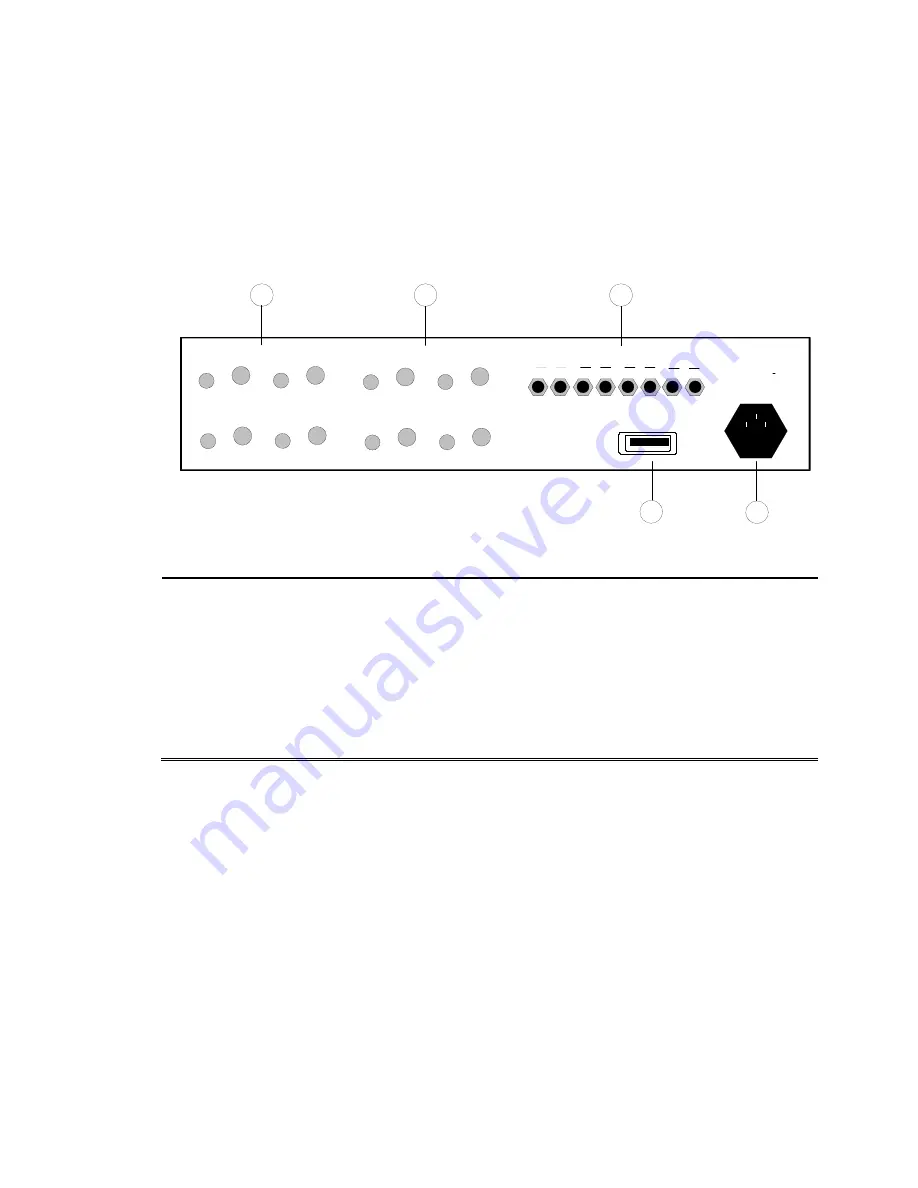
SI-300CC Rear Panel
The following graphic displays port locations on the SI-300CC’s rear panel.
SI-300CC Rear Panel Layout
S1 Video Receiver Ports
IN and OUT ports (for up to four video receivers).
S2 Audio Receiver Ports
IN and OUT ports (for up to four audio receivers).
S3 Fiber Optic Channel Ports
TX (transmit) and RX (receive) ports (for up to four cameras).
S4 IEEE-488 Port
Port used to connect the SI-300CC to a PC to allow remote control of devices
connected to the SI-300CC.
S5 Power Input
Attach AC power cable here.
OUT
IN
Video #1
IN
OUT
Video #3
WARNING
TX
1
2
3
4
RX
TX
RX
TX
RX
TX
RX
Fiber Optic Channels
S1
S2
S3
S4
OUT
OUT
IN
IN
Audio #2
Audio #1
OUT
IN
Audio #4
IN
OUT
Audio #3
IEEE-488
POWER
OUT
IN
Video #2
OUT
IN
Video #4
S5
TDK RF Solutions
Video Camera System
User Manual
5
Содержание VCS-04
Страница 2: ......
Страница 15: ...TDK RF Solutions Video Camera System User Manual 9 ...


