


75
User’s manual
For a better understanding of the PID function it is useful to identify three parts of the controller
structure:
1.
PID input signals. In this section conditioning and setting of the analog references (see
chapterxxx),Frequency reference (see chapter xxxx) and second sensor (see…) is
considered and managed. The output of this part can be used as input to the PID
regulator block.
2.
PID Regulator Block. This is the PID regulator or controller with its parameter and
setting as gains and scaling factors.
3.
PID output signals . This section is used for conditioning and managing the PID
regulator output signal to be used as reference input in the drive.
PID Input signals
there considers three different possible setting of OPD Explorer: Set Point PID
Regulator, Feed back PID Regulator and Manual set point PID Controller.
In all the three different setting the signals coming from the analog inputs AI1,AI2, and AI3, from the
frequency input as speed reference and from the second sensor are eventually either added or
compared together.
With the exception of the feedback setting the reference can be a digital set point with the appropriate
configurations.
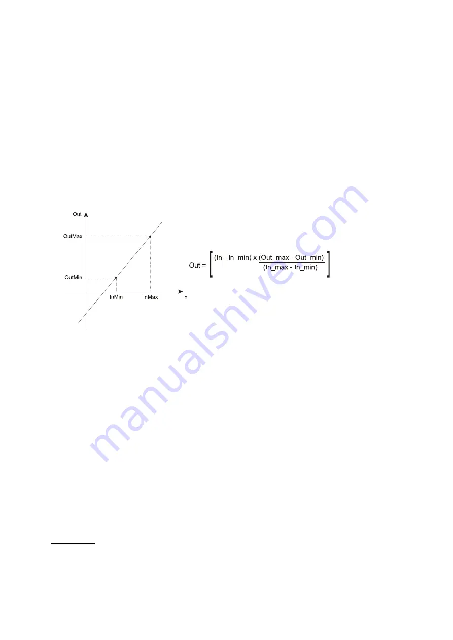
The three generated signals as from above will be then after treated thru a scaling block as here
below written:
With reference to the input signals and specifically for only the manual set point and the reference
set point it is possible to have an acceleration and deceleration time with the appropriate
parameters. The time has to be intended from the
minimum
value to reach the set value and
viceversa.
The PID regulator can work in two different ways as for the actual value of input “auto” handled with a
selector set by parameter P262 and the input I28.
If signal “auto” is “false” PID output is related to the manual set-point, while if “auto” is true the PID
works in automatic way.
With the following premises:
-
Input “SP” is the regulation reference with PID enabled (“auto”=TRUE) displayed thru
internal value “ACT_SP_PID” (D83)
-
Input “PV” is the feedback signal of the regulator with PID enabled (“auto”=TRUE)
displayed thru internal value “ACT_PV_PID” (D85)
-
Input “KP_Filter” defines the time for the first order filter that acts only on the
proportional part
-
Thru input “Man_SP” it is possible to set the output value “XOUT” when PID is disabled
(“auto”=”False”);
-
The PID parameters are:
•
“KP” proportional gain
•
“TI” integral time defined in ms (if set = 0 integral gain is disabled)
•
“TD” derivative time defined in ms (if set = 0 integral gain is disabled)
-
Thru inputs “XMAX” (parameter “LMN_MIN_OUT_PID” P277) and “XMIN” (parameter
“LMN_MIN_OUT_PID” P276) it is possible to limit the regulation value as “XOUT”.
When output “XOUT” reaches its regulation limit the integral part will be freezed and
blocked.
In
manual mode
(Auto = false) PID ouput has following value :
“
Error
” (error value displayed in D92)
= SP - PV
;
“
LMN_P
” (proportional part displayed in D89)
=
0.0
;
“
LMN_I
” (integral part displayed in D90)
=
Man_SP - (KP * Error)
;
“
LMN_D
” (derivative part displayed in D91)
=
0.0
;
“
XOUT
” (PID regulator output displayed in D93)
=
Man_SP
Содержание MINIOPD EXP
Страница 2: ......
Страница 51: ...51 User s manual...
Страница 56: ...56...
Страница 73: ...73 User s manual 3 3 2 PID CONTROLLER...
Страница 74: ...74...
Страница 123: ......