2800 Laura Lane • Middleton, WI 53562 | 800.288.9383 • | www.tcsbasys.com
55
Installation
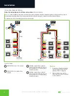
Three-Wire Network Wiring
Follow this wiring diagram for all three-wire systems
(this is common).
NOTES:
In the middle of the network, all network wiring shields should be twisted together and taped off to prevent
accidental grounding. More than one ground on the network wiring can result in communication failure.
A maximum of two terminating resistors can be used.
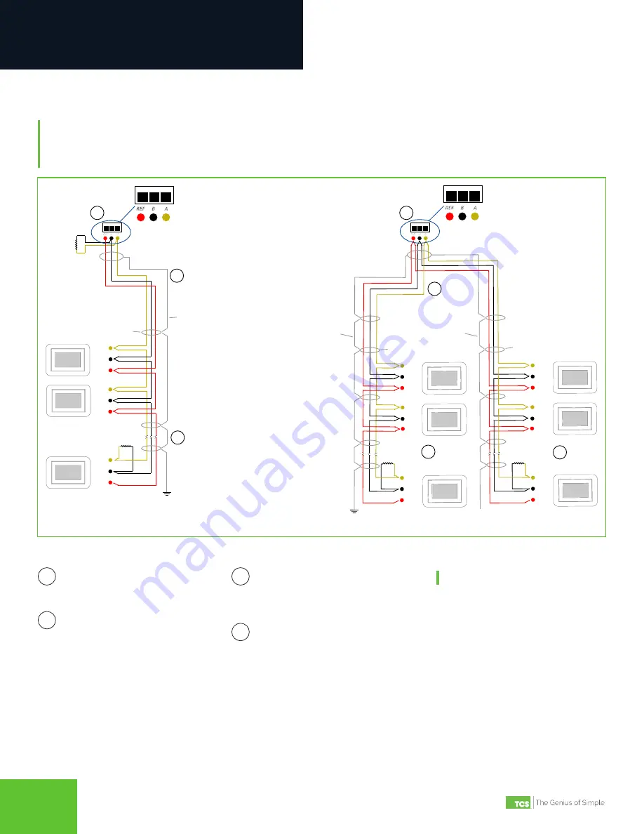
Three-Wire Diagram
QD2040C/D at end of the network.
QD2040C/D in the middle of the
network.
1
3
2
Shielded, twisted three-conductor
communications wiring with one end
earth grounded. (120 Ω terminating
resistors provided.)
Shielded, twisted three-conductor
communications wiring with one end
earth grounded. (120 Ω terminating
resistors provided.)
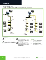
4
NOTES:
1. If using more than 64 controllers,
use the second RS-485 port or
additional QD1010 adapters.
2. Each controller must use the
same baud rate and be assigned
a unique address.
A
B
REF
Shield
A
B
REF
A
B
REF
Earth Ground
Only at one end
Drain
Wire
Last in Daisy Chain
120Ω
Terminating
Resistor
COM 1
REF
A
B
Drain
Wire
120Ω
Terminating
Resistor
A
B
REF
A
B
REF
A
B
REF
Last in Daisy Chain
Shield
Last in Daisy Chain
Earth Ground
Only at one end
120Ω
Terminating
Resistor
A
B
REF
A
B
REF
A
B
REF
Shield
Drain
Wire
COM 1
REF
REF
A
A
B
B
120Ω
Terminating
Resistor
1
2
3
3
4
4
4
COM 1
REF
A
B
COM 1
REF
A
B


