Test and Alignment Specification for RT2841 Series (v0.01).docx
Page 11 of 27
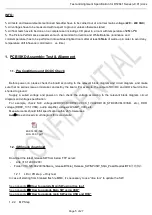
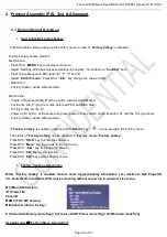
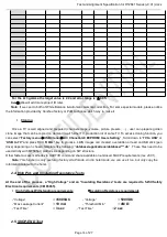
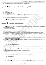
How to enter Main Menu\
- Press RCU “
MENU
” key to display main menu
- Select “Settings
Picture
Advanced setting
Contrast”, Scroll down to “
Contrast
” item
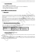
- Press the subsequence RCU keys “
1
”, “
9
”, “
5
” and “
0
”
- Then the Main Menu\ will be displayed on the screen.
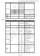
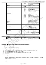
See Appendix
⒁
“Design mode Menu Description”
2.2.Warm-up Test
Following TCL standard and practices, it’s required minimum
15min
of
Warm-Up
that can be considered as Burn-In.
Additional Aging for White Balance alignment is no more necessary due to consistent Picture Performance with
Cloning usage.
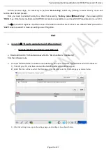
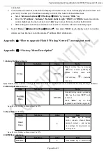
First you need to enable Factory Key. After that selecting“
Factory menu
WARM UP
”, pressing RCU “
OK/►
” key
and then leaving Factory menu by pressing “
Exit
” key. To release/disable Burn-in mode, it’s just required to press
“
Menu
” button from local keyboard. Other faster methods via UART/IR commands are available on enclosed SIACP
requirements (rev. v8.31).
2.3.White Balance & Automatic Gamma correction
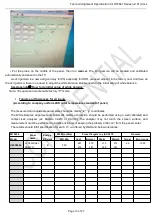
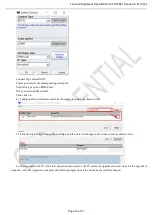
For the white balance & automatic gamma correction, we only need do one of them based on the value of
Align_mode in PDM system or the method gave by AOE or R&D.
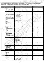
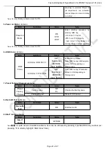
The detail instruction of Align_mode is as below table:
Prop Name
Description
Value
Align_mode
WB alignment or
Auto Gamma correction
0 -- > WB alignment
1-- > Gamma correction
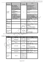
White Balance alignment (Golden sample)
As some color coordinates discrepancies can be noticed from panel batches to others, it may necessary to perform
slight touch-up.
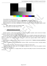
For Color temperature adjustment, switch TV on leading
HDMI
input where should be connected suitable generator
providing following format
1280x720p@60Hz
test pattern. A 32 steps grey scale is recommended to assess relevant
colorimetry tracking and low/high light saturation points.
Содержание RT41VS-EU
Страница 32: ...Test and Alignment Specification for RT2841 Series v0 01 docx Page 27 of 27...
Страница 33: ...11 Oct 18 Page 8 nRT41 Chassis Block Diagram...
Страница 34: ...11 Oct 18 Page 9 nPower supply Block Diagram...
Страница 35: ...11 Oct 18 Page 10 nRT41 Power supply Block Diagram...
Страница 46: ...11 Oct 18 Page 23 nTrouble Shooting...
Страница 47: ...nTrouble Shooting 11 Oct 18 Page 24...
Страница 48: ...nTrouble Shooting 11 Oct 18 Page 25...
Страница 49: ...11 Oct 18 Page 11 nKey Test Point Main Power Supply 12V 12V Test point...
Страница 51: ...11 Oct 18 Page 13 nKey Test Point LDC1 1V5_DDR UDC1 3V3_STB to 1V5_DDR 3V3_STB STR Enable...
Страница 52: ...11 Oct 18 Page 14 LDB1 CORE 1V0 nKey Test Point 12V UDDB 12V TO 1V0...
Страница 53: ...11 Oct 18 Page 15 LDA1 5V nKey Test Point UDA1 12V TO 5V...
Страница 57: ...11 Oct 18 Page 19 nKey Test Point PANEL_VCC 12V Q900 PANEL_VCC...
Страница 58: ...11 Oct 18 Page 20 Main Chip 1 SOC Config 2 24MHz CRYSTAL nKey Test Point Test Point...
Страница 59: ...11 Oct 18 Page 21 nKey Voltage Key Voltage for RTD2841 TCL New Standard RTD2841 POWER 0V Test Point...

