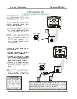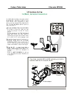
DVD INPUT
Y
Cb
Cr
DVD INPUT
Y
Cb
Cr
IN2
OUT
VIDEO
AUDIO
R
L
-
-
75OHM
ANTENNA
INPUT
DVD INPUT
Y
Cb
Cr
IN2
OUT
VIDEO
AUDIO
R
L
-
-
75OHM
ANTENNA
INPUT
DVD INPUT
Y
Cb
Cr
IN2
OUT
VIDEO
AUDIO
R
L
-
-
75OHM
ANTENNA
INPUT
IN1
AUDIO
VIDEO
S-VIDEO
L
(MONO)
R
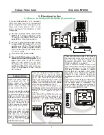
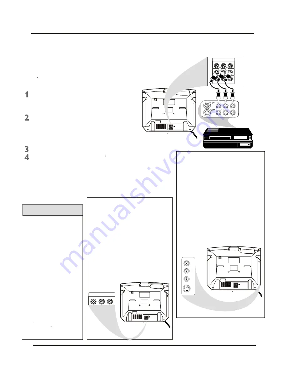
The basic Antenna/Cable TV to Accessory
(VCR, DVD Player, etc.) to TV connection is
shown at right. For other hookups (such as
those with Cable Boxes), refer to the
owner
s manual of the Cable Box or other
Accessories.
Connect a yellow video cable to the
VIDEO IN 2 jack on the rear of the
TV and to the VIDEO OUT jack on
your VCR
(or )
other Accessories.
Connect red and white audio cables
to the AUDIO IN 2 jacks
(left and right)
on the rear of the TV and to the
AUDIO OUT jacks on your VCR
(or
other device.) Match the cable colors
to the jack colors.
Press the TV/AV button on the TV
s
remote control until AV2 appears
in the
upper right corner of the TV screen.
When you play material on the VCR,
DVD player, etc. that is connected to the
AUDIO and VIDEO IN 2 jacks on the rear
of the TV, it will appear on the TV on the
AV 2 channel.
Helpful Hints
Audio and video cables are
not supplied with the TV.
Audio cables are usually
marked with red and white.
Video cables (CVBS) are
usually marked with yellow.
You can connect the antenna
or Cable TV signal to either
the ANTENNA IN jack on your
VCR or to the 75 OHM
Your VCR may not have
Audio and Video Out jacks,
but only an RF or ANTENNA
OUT jack. Use an Therefore
coaxial cable to connect the
VCR
s ANTENNA OUT jack
t o t h e T V
s 7 5 O H M
ANTENNA INPUT jack.
ANTENNA INPUT jack on the
TV. If you connect it to the
VCR, choose TV channels at
the VCR. Connect it to the
VCR if you want to record TV
programming through VCR.
There are Component Video In jacks on
the rear of the TV. These are labelled
DVD Y, Cb and Cr and are red, blue and
green. Use these to connect a DVD
player that has Component Video Out
jacks. This will provide the best picture
quality. Use Component Video cables,
which are not supplied with the TV.
If you connect the DVD player to the
DVD jacks, set the TV to YUV channel to
watch DVD s. Press TV/AV button on the
remote so YUV appears on the TV
screen.
Use either DVD or VIDEO In2 jacks, but
do not use both for the same piece of
equipment. You only need one video
connection per each accessory(DVD
player, etc.).
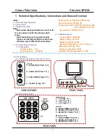
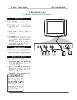
There are AUDIO and VIDEO IN1 jacks at
the lower-right corner of the rear of the TV
set. To view material playing on
equipment connected here, press the
TV/AV so VIDEO 1 is on the TV.
There is also an S-VIDEO IN jack in this
area. Use S-Video connection if your DVD
player, camcorder, etc. has an S-Video
Out jack. S-Video provides a clearer
picture than the standard CVBS video
(the yellow jack). Choose the VIDEO1
channel to view material playing pn
equipment connected to the S-VIDEO IN
jack.
Use either S-VIDEO IN jack or VIDEO IN1
jacks. Do not use both at the same time
for the same piece of equipment. This
would interfere with the picture display. If
both are used, S-VIDEO IN has priority
over the yellow VIDEO In1 jack.
DVD INPUT
Y
Cb
Cr
IN2
OUT
VIDEO
AUDIO
R
L
-
-
R
R
R
Turn on the TV and the VCR.
3. Directions for Use
3.3 Basic to VCR (ACCESSORY)Connection
Colour Television Chassis: M123A
8
Содержание CTR1042
Страница 41: ...Colour Television Chassis M123A 41 6 Block Diagram and I2C 6 1 Block Diagram...
Страница 48: ...Colour Television Chassis M123A 48 7 Electrical Diagrams 7 8 Side AV 7 Electrical Diagrams 7 9 Audio Amplifier...
Страница 49: ...Colour Television Chassis M123A 49 7 Electrical Diagrams 7 10 CRT Panel...
Страница 52: ...Colour Television Chassis M123A 52 8 PCB 8 1 Main PCB...
Страница 53: ...Colour Television Chassis M123A 53 8 PCB 8 2 CRT PCB...
Страница 54: ...Colour Television Chassis M123A 54 8 PCB 8 3 MPX PCB...
Страница 55: ...Colour Television Chassis M123A 55 8 PCB 8 4 SIDE AV PCB...


