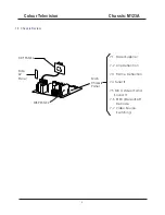
--- In order to prevent damage to ICs and transistors, avoid all high voltage flashovers. In order to
prevent damage to the picture tube, use the method shown in Fig. 2-1, to discharge the picture
tube. Use a high voltage probe and a multi-meter (position VDC). Discharge until the meter
reading is 0 V (after approx. 30 s).
---- All ICs and many other semiconductors are susceptible to electrostatic discharges (ESD)
Careless handling during repair can reduce life drastically. When repairing, make sure that you
are connected with the same potential as the mass of the set by a wristband with resistance.
Keep components and tools also at this potential. Available ESD protection equipment:
--- Complete kit ESD3 (small tablemat, wristband, connection box, extension cable, and ground
cable)
--- Wristband tester
--- Together with the deflection unit and any multi-pole unit, flat square picture tubes form an
integrated unit. The deflection and the multi-pole units are set optimally at the factory.
Adjustment of this unit during repair is therefore not recommended.
---- Be careful during measurements in the high voltage section and on the picture tube.
Never replace modules or other components while the unit is switched ON.
---- When you align the set, use plastic rather than metal tools. This will prevent any short circuits
and the danger of a circuit becoming unstable.
--- Measure the voltages and waveforms with regard to the chassis (= tuner) ground (), or hot
ground (), depending on the area of circuitry being tested.
---- The voltages and waveforms shown in the diagrams are indicative. Measure them in the Service
Default Mode (see chapter 5) with a color bar signal and stereo sound (L: 3 kHz, R: 1 kHz unless
stated otherwise) and picture carrier at 475.25 MHz (PAL) or 61.25 MHz (NTSC, channel 3).
---- Where necessary, measure the waveforms and voltages with () and without () aerial signal.
Measure the voltages in the power supply section both in normal operation () and in standby ().
These values are indicated by means of the appropriate symbols.
---- The picture tube panel has printed spark gaps. Each spark gap is connected between an
electrode of the picture tube and the Aquadag coating.
--- The semiconductors indicated in the circuit diagram and in the parts lists are completely
interchangeable per position with the semiconductors in the unit, irrespective of the type
Indication on these semiconductors.
2.3 Warnings
_
4822 344 13999.
2.4 Notes
Colour Television Chassis: M123A
5
Содержание CTR1042
Страница 41: ...Colour Television Chassis M123A 41 6 Block Diagram and I2C 6 1 Block Diagram...
Страница 48: ...Colour Television Chassis M123A 48 7 Electrical Diagrams 7 8 Side AV 7 Electrical Diagrams 7 9 Audio Amplifier...
Страница 49: ...Colour Television Chassis M123A 49 7 Electrical Diagrams 7 10 CRT Panel...
Страница 52: ...Colour Television Chassis M123A 52 8 PCB 8 1 Main PCB...
Страница 53: ...Colour Television Chassis M123A 53 8 PCB 8 2 CRT PCB...
Страница 54: ...Colour Television Chassis M123A 54 8 PCB 8 3 MPX PCB...
Страница 55: ...Colour Television Chassis M123A 55 8 PCB 8 4 SIDE AV PCB...


