Colour Television Chassis: M123A
dd
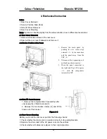
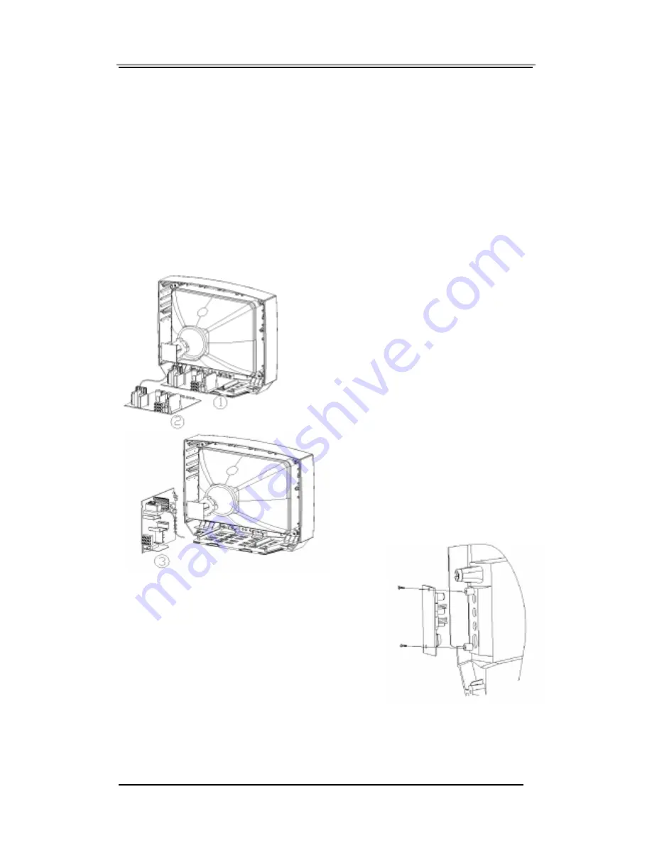
1. Remove the complete Side I/O assembly after
unscrewing the 2 fixation screws [1].
2. Release the two fixation clamps [2] and lift the
board out of the bracket
Figure 4-2
4. Mechanical Instruction
Index:
1. Rear Cover Removal
2. Service Position Main Panel
3. Side I/O Panel Removal
4. Rear Cover Mounting
Note:
Figures can deviate slightly from the actual situation, due to different set executions.
4.1 Rear Cover Removal
1. Remove all fixation screws of the rear cover.
2. Now pull the rear cover backward and remove it.
4.2 Service Position Main Panel
4.3 Side I/O Panel Removal
.
4.4 Rear Cover Mounting
Before you mount the rear cover, perform the following checks:
1. Check whether the mains cord is mounted correctly in its guiding brackets.
2. Replace the strain relief of the AC power cord into the cabinet.
3. Check whether all cables are replaced in their original position.
1.
Remove the main panel, by
pushing the two center clips
outward <1>. At the same time
pull the panel away from the
CRT <2>.
2.
Disconnect the degaussing coil
and load speaker connector.
3.
Move the panel somewhat to
the right and flip it 90 degrees
<3>, with the components
towards the CRT.
Содержание CTR1042
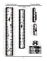
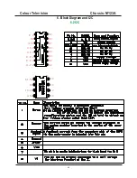
Страница 41: ...Colour Television Chassis M123A 41 6 Block Diagram and I2C 6 1 Block Diagram...
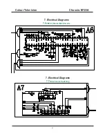
Страница 48: ...Colour Television Chassis M123A 48 7 Electrical Diagrams 7 8 Side AV 7 Electrical Diagrams 7 9 Audio Amplifier...
Страница 49: ...Colour Television Chassis M123A 49 7 Electrical Diagrams 7 10 CRT Panel...
Страница 52: ...Colour Television Chassis M123A 52 8 PCB 8 1 Main PCB...
Страница 53: ...Colour Television Chassis M123A 53 8 PCB 8 2 CRT PCB...
Страница 54: ...Colour Television Chassis M123A 54 8 PCB 8 3 MPX PCB...
Страница 55: ...Colour Television Chassis M123A 55 8 PCB 8 4 SIDE AV PCB...


