TC Electronic DB2 Скачать руководство пользователя страница 9

14

15

THE TC ICON EDITOR

Basic Operation

The 

Icon Link

 button in the upper left corner 

allows you to navigate between two main 

pages/modes.

Fig 1 – Setup/Select Page

Via the “overall” Select & Setup pages 

you can access overall settings and make 

choices such as:

•  Selecting which of the connected units you 

want to operate.

•  Enabling devices for networking.

•  Making TC Icon settings (such as display and 

fader appearance).

On the Select page shown above (Fig. 1), all 

connected units will appear. Click on one of the 

units shown on that page.

Auto Page

This page is not required for operating a DB2.

Fig 2 – Operating pages

Click the 

Icon Link

 button in the upper left 

corner to select these pages.

These pages are relevant to one specific unit.

Library pages handle operations such as 

recalling, storing and deleting presets.

System pages handle overall clock settings, I/O 

settings and network settings.

Engine pages allow you to control all algorithm-

specific processing parameters.

Renaming Presets

All user presets can easily be renamed.
Click on the CURRENT ENGINE NAME button 

on the Store page. A keyboard display will open.

Please note that entering the name and 

pressing ENTER does not permanently 

store the new name. To actually store 

a preset, you have to click the STORE 

button on the Store page.

Fader Assign

The Fader Assign button allows you to assign 

any algorithm parameter to any of the six 

Faders. This means that you are not limited to 

operating the parameters visible on the current 

page. You can have e.g. the In Gain parameter 

from the Main page assigned to Fader 1, the 

Loudness Level Trim from the Loudness page 

assigned to Fader 2 etc.

To assign a parameter:

•  Click the Fader Assign button.

•  Select the Fader you wish to link a parameter 

to by clicking the field just above the fader.

•  Click the parameter you wish to link to the 

selected fader.

Introduction

The TC Icon Software Editor is a generic editor 

that currently controls the following products 

by TC Electronic: System 6000, DB-8/DB-4/

P2/Reverb4000 and DB2. In this section only 

subjects relevant for usage with the DB2 will be 

discussed.

DB2 is connected to your computer via a serial 

COM port (RS232) or via the supplied RS232-

to-USB converter.

Please note that RS232 can be used 

over long distances (up to 200 meters), 

whereas the cable length should not 

exceed 10 meters when the RS232 to 

USB converter is used.

Navigating the Software Editor or TC Icon 

display is easy once you have grasped the 

basic concepts explained in the following 

section.

Basics:

•  Click the top tabs to make primary selections.

•  Click the side tabs or elements to make 

secondary selections.

•  On the Setup/UI page select either “Faders 

at bottom” or “Fader at Right Side”.

•  Click on parameter value fields to instantly 

assign parameters to Fader 6.

•  Adjust values using Faders 1 to 6. (Also see 

the explanation of LINK on next page.)

Unpacked and ready

•  Connect the DB2 according to the illustra

-

tions on page 12.

•  Install the software according to the explana

-

tions on the previous page of this manual.

•  Power up DB2 and start the TC Icon 

software on your computer.

•  Go to the Setup/Devices/Ports page to select 

the COM port (1 to 4) to which you have 

connected the DB2.

•  Select the correct port. (Note that when you 

open the Setup Port page for the first time, 

all COM ports – 1 to 4 – are selected).

Another active application may access 

the selected COM Port, resulting in a 

conflict. If this is the case, you should 

close that application or connect the DB2 to 

another COM port. Also see this manual’s 

“Troubleshooting” section.

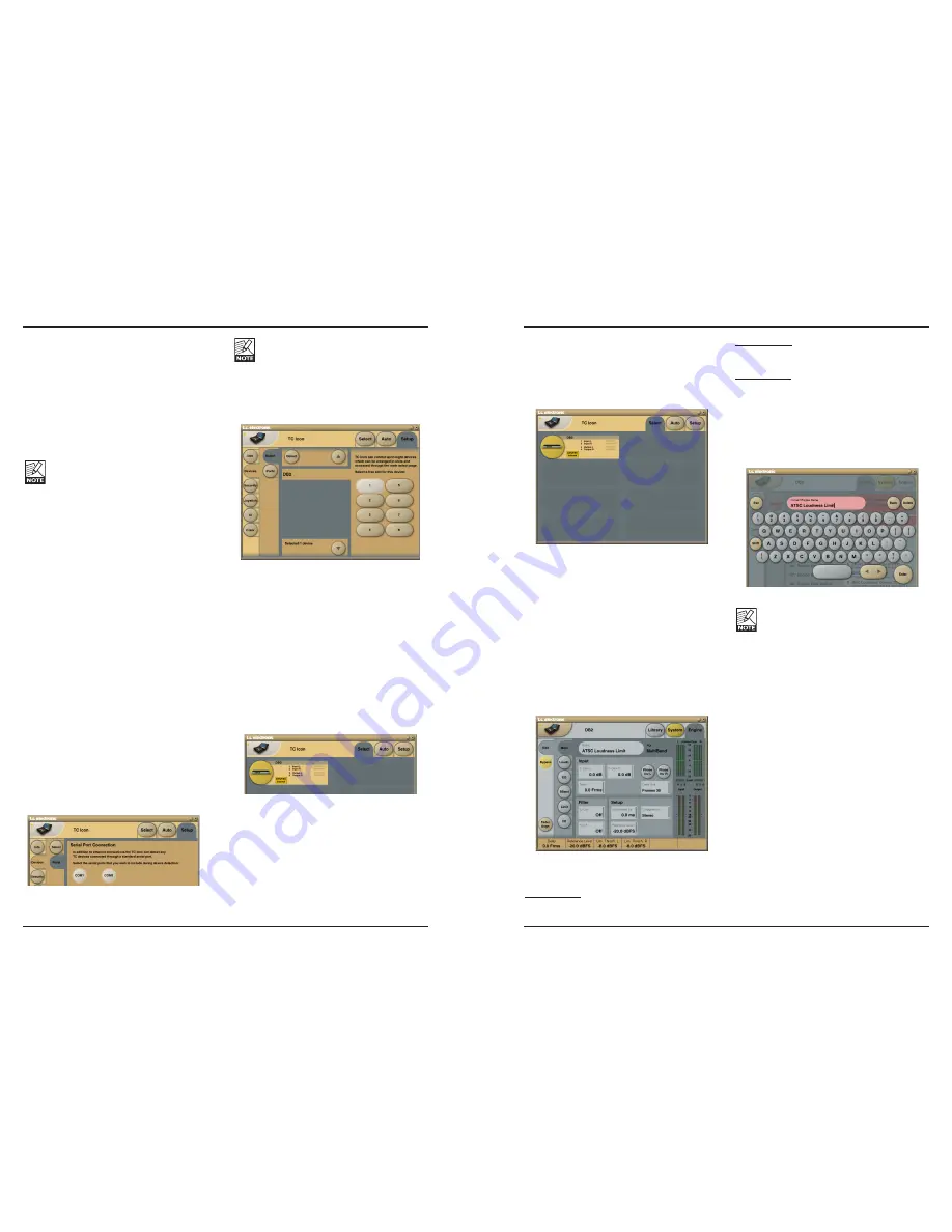
•  Go to the TC Icon Setup/Devices page.

•  Click the DETECT button. The TC Icon Editor 

will scan the System and find the connected 

DB2’s.

•  When the connected DB2 is detected, 

assign the unit to one of the eight shortcut 

buttons on the right side of the display by 

clicking one of the eight buttons (see above). 

Any button will do. When several units are 

connected, this page serves as a convenient 

organizer for the entire system.

•  Go to the Select page (top tab), and you will 

see a screen similar to the one below. The 

number of connected units and their locations 

may vary depending on your specific setup.

•  Click the large DB2 button.

•  TC Icon now retrieves data from the DB2.

•  When ready you will see the Main operating 

display.

THE TC ICON EDITOR

Содержание DB2

Страница 1: ...DB2 LOUDNESS CONSISTENCY PROCESSOR USER S MANUAL...

Страница 2: ...as been dropped This equipment should be installed near the socket outlet and disconnection of the device should be easily accessible To completely disconnect from AC mains disconnect the power supply...

Страница 3: ...ent lighting control apparatus for professional use Part 1 Emission EN 55103 2 Product family standard for audio video audio visual and entertainment lighting control apparatus for professional use Pa...

Страница 4: ...Step by Step With the launch of DB2 TC Electronic also introduces a new commitment to buyers of any DB processor Within two years of the original purchase users may upgrade DB2 to DB4 or DB8 and DB4 t...

Страница 5: ...e DB2 s card slot Go to the TC Icon System Card page Decide whether you wish to exclude the System Preset that hold overall Clock settings Analog Trim levels Dither Status Bit settings and GPI setting...

Страница 6: ...rently recalled preset has been edited but not stored GAIN Meter Indicates the current Loudness correction gain as per ITU R BS 1770 or ITU R BS 1770 2 OPTIMIZE Meters Indicates gain reduction in the...

Страница 7: ...2 9 pin Sub D BNC Sync In GPI IN RS232 For connecting to a PC RS232 port use a standard 9 pin Sub D cable Supplied For connecting to a PC USB port use the supplied RS232 to USB connector Note max reco...

Страница 8: ...tart the installation of the TC Icon Software Editor will proceed Follow the instructions A TC Icon shortcut will appear both on the desktop and in the Start menu The MS installer is a small installat...

Страница 9: ...nly subjects relevant for usage with the DB2 will be discussed DB2 is connected to your computer via a serial COM port RS232 or via the supplied RS232 to USB converter Please note that RS232 can be us...

Страница 10: ...page User Presets The User banks U1 to U8 can hold up to eight presets each Factory Presets DB2 comes loaded from the factory with a collection of general purpose factory presets organized in banks F...

Страница 11: ...ital SRC is selected on the Engine I O page Analog Trim Input Trim L Input Trim R Range 1 00 to 1 00 dB in 0 05 dB increments Level trim for analog inputs Output Trim L Output Trim R Range 1 00 to 1 0...

Страница 12: ...as a fraction of Vs and as a guideline typical voltages when Vs 5 000 V If the supply voltage is e g 5 015 V the table should be corrected by multiplying these values by 5 015 5 GPI Implementation Thr...

Страница 13: ...or the two yellow digits on the In Out meters SYSTEM NET PAGE ICON VIEWS The upper part of this page holds information on the current software versions and the serial number of the accessed unit Netwo...

Страница 14: ...the set Analog Scale Output level MAIN PAGE Input In Gain Range 0 dB to Off There are separate level controls for the left and right Input A and B Phase Inv L R Range Normal Inverted Click to invert t...

Страница 15: ...l is relative to Reference Level on the Main Page Add Target Level to Reference Level to calculate the target loudness level When Loudness Measure is set to BS 1770 2 the calculation will have the uni...

Страница 16: ...s adjustments EQ PAGE Introduction DB2 features a digital three band parametric EQ with high pass and low pass filters switch able between Notch Parametric Shelving and Cut types The needle sharp notc...

Страница 17: ...Mid Gain 12 dB to 12 dB Hi Gain 12 dB to 12 dB Range for the Notch filter Lo Gain 100 dB to 0 dB Mid Gain 100 dB to 0 dB Hi Gain 100 dB to 0 dB EQ PAGE Type Click TYPE and use Faders 1 to 3 to set the...

Страница 18: ...pplied from the multiband system Below the Defeat Threshold the frequency response is flat and gain is unity Defeat Threshold is relative to Compressor Threshold which is relative to Reference Level D...

Страница 19: ...h between emphasis Off HD and normal DTV broadcast 50 microsec 75 microsec and J17 NICAM emphasis Note When pro nounced Emphasis Limiting is required it is normally advisable to link the limiters to a...

Страница 20: ...r BNC AES3 id 75 ohm RCA Phono S PDIF AES3 id 24 bit S PDIF 24 bit EIAJ CP 340 IEC 958 HPF TPDF dither 8 to 24 bit BNC 75 ohm 0 6 to 10 Vpp 32 kHz 44 1 kHz 48 kHz 0 5 ms 48 kHz 0 to 1000 ms 24 bit at...

Страница 21: ...higher For AC3 transmission however the Limit Threshold should not go much above 6 dBFS to avoid distortion in consumer devices If DB2 is processing for a low dynamic range platform such as IPTV or Mo...

Страница 22: ...cable The Input meters will show 0 dB The symbol will indicate that the test is positive The symbol will indicate that there is a problem with the input or the output Test 4 RS232 remote I O Test Con...

Страница 23: ......

Отзывы: