


INSTALLATION - ICON EDITOR
Requirements for running the TC Icon
Software Editor
• A PC with a Pentium or compatible processor
with one of the following operating systems:
Windows 95, Windows 98, Windows NT,
Windows 2000, Windows ME, Windows XP
and Windows Vista.
The CD-ROM
The CD-ROM delivered with the TC Icon
Software Editor contains:
• A folder called “TC Icon Software Editor –
Update version“. Use the contents of this
folder if the MS Installer* has already been
installed on your computer.
• A folder called “TC Icon Software
MS Installer” (use the contents of this folder
if MS Installer has not been installed on your
computer – see below)
• The DB2 Manual in PDF format.
Installing
the TC Icon Software Editor
Your computer probably holds the required MS
Installer program and you only need to run the
file called: TC Icon x.xx.msi
This file is located on the CD in the folder
called:
“TC Icon Software Editor – Update Version”
• Exit all programs currently running on your
computer and open the CD contents in
Windows Explorer.
• Open the folder called “TC Icon Software
Editor – Update Version”.
• Copy the file called “TC Icon x.xx.msi” to a
location on your computer’s hard drive.
• Double-click the icon and follow the instruc
-
tions.
A “TC Icon” shortcut will appear both on the
desktop and in the Start menu.
Problems?
If during the process described above you
have discovered that the required MS Installer
program is NOT already installed on your
computer, you should run the installation file
including the MS installer: TC Icon x.xx.zip
This file is located in the folder called:
TC Icon Software Microsoft Installer.
This file includes both the Microsoft Installer
Service and the TC Icon Software Editor.
• Exit all programs currently running on your
computer and open the CD contents in
Windows Explorer.
• Open the folder “TC Icon Software
MS Installer” and double-click on “TC Icon
x.xx.zip”.
• Select a location to unzip the files to.
“Windows/Temp” is automatically suggested.
• Click FINISH.
• Restart your computer when prompted to.
• After restart, the installation of the TC Icon
Software Editor will proceed.
• Follow the instructions.
A “TC Icon” shortcut will appear both on the
desktop and in the Start menu.
* The MS installer is a small installation program by Microsoft
which is required to run a regular .msi-update. The program is
installed on most computers running Windows 98 SE and up.
DB2 needs Icon software 4.01 or higher
for correct operation
12
13
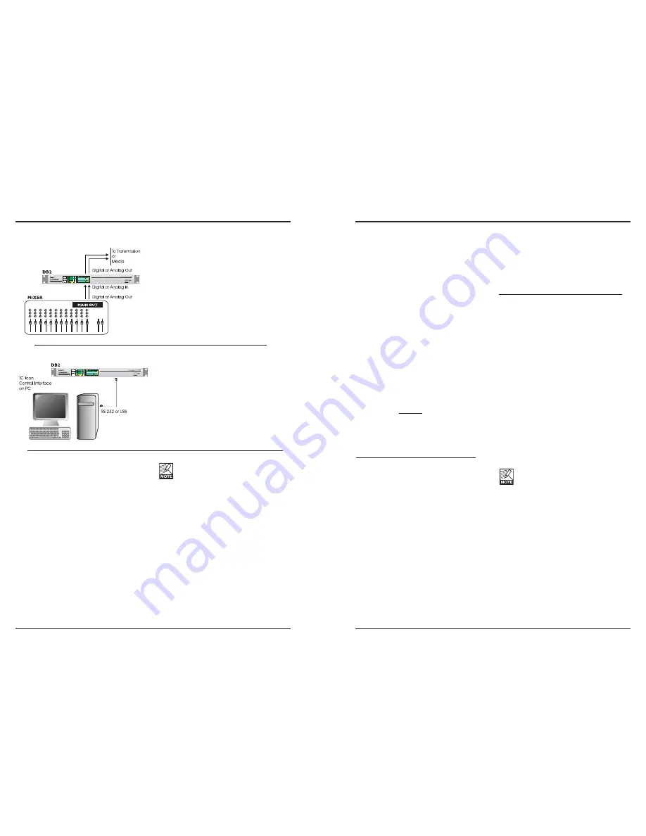
TYPICAL SETUPS
Connecting and Setting up the DB2
In use – no TC Icon Editor/PC connection
necessary.
• Connect your audio source material to DB2
Inputs. Options are balanced Analog, digital
AES3-id or S/PDIF.
• Connect Outputs to relevant media.
Standard Setup
• Connect a free RS232 serial COM port on
the computer to the RS232 connection on the
rear of DB2. Use the supplied RS232 to USB
connector when connecting to USB.
(Note max. verified USB cable length is 10 m)
• Start the TC Icon PC Editor and select appro
-
priate COM port.
(Read TC Icon installation procedure section)
Make audio connections if these are necessary
for programming.
ALL DATA previously stored on the card
will be destroyed when formatting the
card! If the card is write-protected, no
data can be written on the card. The
protect/unprotect switch is located at the
edge of the card.
• Remove the card and go to the target DB2
unit.
• Power off the target DB2 unit.
• Insert the card and power up using the front
panel POWER key while holding the OK key
pressed. Press UTILITY until the display
shows “C” (CLONE).
• Now press the OK key. All settings (with or
without “System Preset”, depending on your
previous selection) are now copied to the
target DB2.
Cloning DB2’s using a PCMCIA card
Once a single DB2 has been set up for the
desired applications, other DB2’s in the house
can be easily cloned using a standard PCMCIA
card. In other words; it is NOT necessary to
hook up every single DB2 to a computer to set
these up.
• Insert an unprotected PCMCIA card into the
source DB2’s card slot.
• Go to the TC Icon System/Card page.
• Decide whether you wish to exclude the
System Preset that hold overall Clock
settings, Analog Trim levels, Dither, Status
Bit settings and GPI settings. To exclude the
System Preset, activate the “Exclude System
Preset” button.
Then click CREATE CLONE CARD.
Содержание DB2
Страница 1: ...DB2 LOUDNESS CONSISTENCY PROCESSOR USER S MANUAL...
Страница 23: ......


