background image

40/ 42 

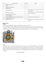
Crankcase 

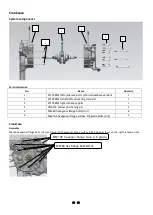
System components 


Parts information 

No. 

Name 

Quantity 

1.


ZT1P58MJ 

left crankcase parts (short wheelbase version)


2.


ZT1P58MJ crankshaft connecting rod parts 

3.


ZT1P58MJ right crankcase parts 

4.


Φ10×14 hollow positioning pin


5.


M6×60 hexagonal flange bolts (zinc

)


6.


M6×105 hexagonal flange surface 9.8 grade bolts (zinc

)


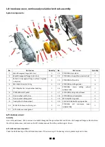
Crankcase 

Assembly 

M6×60 hexagonal flange bolts (zinc

) and 3 m6×105 hexagonal flange surface 9.8 grade bolts (

zinc

) on the right crankcase side)


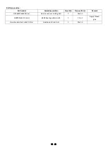
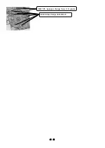
M6×105 hexagon flange face 9.8 grade


M6×60 hex flange bolts

M8×25   


Содержание ZT1P52MI

Страница 1: ...1 42 ZT1P52MI Engine maintenance manual 2023 04 01...

Страница 2: ...t codes on the official website of ZONTES which will not be listed in detail in this manual if the names of parts in this manual are inconsistent with the official website of ZONTES the official websi...

Страница 3: ...arts etc reducing the service life It should be wiped with a non woven cloth that will not leave residues Ordinary rags may leave rags or wool that will affect assembly or cause other adverse effects...

Страница 4: ...ts 21 Electric starter box cover 22 Start agency 23 Timing chain 23 Oil pump right crankcase cover 24 System components 24 Right crankcase cover 25 Oil pump 25 Oil filter 26 System components 26 Oil f...

Страница 5: ...5 42 System components 40 Crankcase 40...

Страница 6: ...ed sleeve head 16 and pre tighten it with a torque wrench to fix the torque the torque is 14 1 N m Cylinder compression test 1 Start the engine warm up the engine to normal operating temperature and t...

Страница 7: ...ine rubber oil seal 1 7 Water seal moving ring ceramics 1 17 16 5 7 5 water plug 1 8 ZT1P58MJ water pump blade 1 18 18 2 2 4 EPDM rubber O ring 1 9 M6 10 top pin bolt zinc 1 19 Gb t 276 6000 p5c3 deep...

Страница 8: ...it to the position shown in the figure below After installation measure the depth to confirm whether it is installed in place Remarks apply engine oil to the oil seal installation hole and install th...

Страница 9: ...sealing ring on the water pump cover groove if the O ring is trimmed or worn replace it with a new one and finally take 4 m6 22 full threaded bolts on the hexagonal flange surface grade 8 8 zinc one...

Страница 10: ...M6 10 top pin bolt zinc 1 Tool t sleeve 8 fixed torque 10 1 N m 7 ZT1P58MJ intake rocker arm subassembly b 1 8 ZT1P58MJ camshaft bearing pressure plate 1 9 M5 15 5 hexagon socket head screw 2 Apply t...

Страница 11: ...Gb16674 M8 25 bolts diagonally at t rod 10 and remove the cylinder head cover cylinder head cover rubber pad and 8 14 hollow positioning pin in sequence Note when removing the cylinder head cover the...

Страница 12: ...oint t turns over the marking line it cannot be rotated in the opposite direction It is necessary to turn the crankshaft clockwise two times again to re align the point 3 As shown in the picture remov...

Страница 13: ...ocker arm mark E have no abnormal wear and the rollers of the intake and exhaust rocker arms rotate smoothly without abnormal noise 4 Check that the intake and exhaust springs have no cracks or abnorm...

Страница 14: ...shown in the figure install the camshaft bearing pressure plate apply an appropriate amount of thread fastening glue on the surface of 1 m6x10 and 2 m5x15 bolts after screwing in pre tighten and set t...

Страница 15: ...s on the side use the fixed torque wrench to tighten respectively nut 8 3 17 2 iron gasket should not be missed m8 1 25 hexagonal flange nut fixed torque 25 3 N m m6 105 hexagonal flange bolts with a...

Страница 16: ...manual for disassembly and assembly cylinder head cover cylinder head cylinder head cover Cylinder head assembly refer to ZT1P52MI engine maintenance manual for disassembly and assembly cylinder head...

Страница 17: ...r damaged it needs to be replaced Tensioner installation 1 Tighten the tensioner ejector rod with a one word batch rotate the one word batch clockwise while holding the tensioner ejector rod with your...

Страница 18: ...pin bolt 1 Tool t sleeve 8 fixed torque 10 1 N m 4 Cylinder head gasket 1 Cannot be reused 5 Cylinder block gasket 1 Cannot be reused 6 10 14 hollow positioning pin 2 7 Oil ring combination 1 8 16 1...

Страница 19: ...ton ring 1 Remove the combination of the first air ring the second air ring and the oil ring Tip To remove the piston ring open the end notch by hand and lift the other side of the ring over the top o...

Страница 20: ...he piston ring are staggered for assembly the arrow on the top of the piston points to the exhaust side as shown in the figure Remarks before installing the cylinder block apply an appropriate amount...

Страница 21: ...aust side do not install it backwards Electric starter box cover starter mechanism timing chain System components No Material name Quantity Remark 1 15 6 1 9 fluorine rubber O ring 1 2 16 30 9 bushing...

Страница 22: ...ctric starter box cover and take out the electric starter box cover 16 30 9 bushing 15 6 1 9 fluorine rubber O ring and positioning pin Inspection 1 Check the electric starter box cover oil seal 151 3...

Страница 23: ...earing etc Have no abnormal wear Install 1 Install the ZT1P58MJ electric starter gear assembly 19 4 27 8 3 6 bushing cg 78h overrunning clutch ZT1P58MJ electric starter reduction gear shaft and ZT1P58...

Страница 24: ...ming chain check the timing chain if there is no sticking crack or deformation it is qualified Install 1 Put the timing chain on the timing drive gear of the crankshaft take 2 m6 10 top pin bolts and...

Страница 25: ...bolt of the right crankcase cover and take out the right crankcase cover right crankcase cover gasket and positioning pin Inspection 1 check that the right crankcase cover oil seal FB22 32 7 fluorine...

Страница 26: ...t the corresponding position of the right crankcase take 2 m5 15 5 inner hexagonal cylindrical screws and apply an appropriate amount of thread glue after screwing in tighten with a fixed torque torqu...

Страница 27: ...MJ engine oil filter sealing ring is first inserted into the corresponding position of the oil filter and the end of the oil filter with the sealing ring is inserted into the boss at the corresponding...

Страница 28: ...r fixture to prevent the rotor from rotating freely use a torque wrench or electric gun and a sleeve 17 to remove the m12 1 25 hexagonal flange surface 10 level nut and remove the 12 5 23 1 8 gasket s...

Страница 29: ...mponents of the magneto stator on the corresponding position of the right crankcase cover apply an appropriate amount of thread glue on the threads of three GB70 1 M6 25 bolts and three M6 16 bolts an...

Страница 30: ...sleeve 1 7 Driven wheel clutch shoe 3 18 ZT1P52MI main fixed plate 1 8 Driven wheel sliding plate 1 19 12 2 29 2 5 gasket 2 9 Fixed plate of driven wheel 1 20 12 24 2 6 Belleville spring washer 1 10 1...

Страница 31: ...embly together Pinch the main sliding wheel subassembly and the ramp plate inside and remove it together with the driving wheel bushing Inspection Check whether the centrifugal roller is worn and out...

Страница 32: ...d then assemble it on the crankshaft and assemble it in place Put the 12 2 29 2 5 washer and 12 24 2 6 butterfly spring washer on the crankshaft in turn and then screw the m12 1 25 hexagonal flange su...

Страница 33: ...tioning pin 2 15 Gb276 6302 p5c3 deep groove ball bearings nitrided 1 5 Gb276 60 28 2rk deep groove ball bearings koyo 1 16 6 2 19 2 5 spacers 1 6 Gb276 6302 p5c3 deep groove ball bearings nitrided 2...

Страница 34: ...l Assembly position Quantity Torque N m Remark Gb16674m8 40 zinc Gear case cover locking bolt 7 20 2 5 Gb5789m6 12 zinc 6204 bearing platen bolts 1 1 0 1 Apply thread glue Non standard bolt m8 25 zinc...

Страница 35: ...ce Inspection 1 Check the gear case cover bearing and oil seal Turn the inner ring of the bearing by hand and the bearing turns smoothly and silently If the bearing rotation is stuck please replace th...

Страница 36: ...h bearing in the gearbox install the duplex gear assembly and output gear in sequence and spray engine oil on each part in the same way Assemble the output shaft with the retaining ring fully installe...

Страница 37: ...il volume Gearbox oil Routine maintenance without disassembling the gearbox 160ml Non routine maintenance disassembly of gearbox 170ml 3 After the assembly is completed wipe off the oil stains around...

Страница 38: ...terial name Quantity 1 ZT1P58MJ thermostat subassembly 1 2 16 5 1 95 EPDM o ring 1 3 ZT1P58MJ right crankcase parts 1 4 ZT1P58MJ fan box cover subassembly 1 5 M6 60 hexagonal flange bolts zinc 5 6 ZT1...

Страница 39: ...al flange bolts zinc and pre tighten them diagonally and then use the fixed torque wrench to fix the torque the torque is 12 1 5 N m 2 Put the no problem or brand new radiator in the corresponding pos...

Страница 40: ...1P58MJ right crankcase parts 1 4 10 14 hollow positioning pin 2 5 M6 60 hexagonal flange bolts zinc 8 6 M6 105 hexagonal flange surface 9 8 grade bolts zinc 3 Crankcase Assembly M6 60 hexagonal flange...

Страница 41: ...e the corresponding crankcase should be replaced Install Loctite 5900 plane sealant evenly and continuously on the joint surface of the left crankcase note if there is uneven glue application or even...

Страница 42: ...42 42 M6 105 hexagon flange face 9 8 grade M6 60 hex flange boltsM8 25...

Отзывы: