12
Controls and Systems
Model SB25
PC Connection
The SB25 can be connected to a PC in order to
manage recipes and system calibration, using the
supplied software. A PC running Windows XP or
greater with a USB port is required.
1.
Remove the cover from the upper USB port on
the left side of the system by unscrewing the
cap counter-clockwise.
2.
Connect the USB cable from the PC to the
USB-B connector on the unit.
3.
Switch the main power ON.
4.
The first time you connect to the unit and start
the PC software, you may be prompted to
install the proper drivers on your PC. Follow the
on screen instructions to install the proper
drivers.
Note: This requires an Internet
connection.
5.
Open the programming software:
“OTGConfig Rels Rev A.exe”
6.
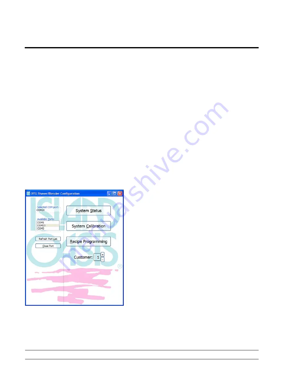
Refresh the Port List and select the proper
COM Port from the list of Available Ports. This
is usually the highest numbered port in the list.
(See Figure 3.)
Figure 3
7.
To reset the connection select “Close Port” and
reselect.
Customer Numbers
Two customer numbers can be stored in the
shaver/blender controller PCA memory, containing
separate recipe and calibration settings. These are
selected by a DIP switch setting inside the system,
located on the top edge of the dispense PCA
assembly. Position 5 is used to select the customer
number. (Position 6 is used to enable or disable the
cane pump option on the SB25, if it is functioning.)
S
Customer 1 - Switch Position 5 OFF
S
Customer 2 - Switch Position 5 ON
When you power up the system, the customer
selected number is displayed briefly (one second)
before showing the default menu settings.
S
If recipe key 1 is on briefly at power up, the
DIP switch is set to customer 1.
S
If recipe key 2 is on briefly at power up, the
DIP switch is set to customer 2.
Customer configurations are generated in the
supplied PC software. The main page of the
supplied software will indicate the current DIP switch
setting. Any combination of customer configurations
can be loaded into the system. If you select a
configuration that hasn't been downloaded, the
default values in the software will be used.
Содержание SB25
Страница 2: ......
Страница 9: ...5 Model SB25 Introduction SB25 Specifications Continued...
Страница 14: ...10 Controls and Systems Model SB25 Control Overview Figure 1...
Страница 40: ...36 Controls and Systems Model SB25 Notes...
Страница 49: ...45 Model SB25 Parts Section 4 Parts S Warranty Explanation S Exploded Views S Parts List S Wiring Diagram...
Страница 57: ...53 Model SB25 Parts Model SB25 Drain Assembly E 2014 Carrier Commercial Refrigeration Inc Figure 56...


