background image

OPERATOR'S
MANUAL

Model 432 Tim Hortons

Slush Freezer

Original Operating Instructions

068462-M

10/8/10 (Original Publication)

Updated 1/23/15

Содержание 432

Страница 1: ...OPERATOR S MANUAL Model 432 Tim Hortons Slush Freezer Original Operating Instructions 068462 M 10 8 10 Original Publication Updated 1 23 15...

Страница 2: ...ercial Refrigeration Inc 068462 M Any unauthorized reproduction disclosure or distribution of copies by any person of any portion of this work may be a violation of Copyright Law of the United States...

Страница 3: ...Operator Parts Identification 8 432 Exploded View 8 Beater Door Assembly 10 Accessories 12 Section 5 Important To the Operator 13 Power Switch 14 Reset Button 14 Display Light Switch 14 Indicator Ligh...

Страница 4: ...ual is subject to change without notice Note Only instructions originating from the factory or its authorized translation representative s are considered to be the original set of instructions 2010 Ca...

Страница 5: ...prior to performing any repairs Failure to follow this instruction may result in personal injury or death from electrical shock or hazardous moving parts as well as poor performance or damage to the...

Страница 6: ...VERE PERSONAL INJURY FROM ELECTRICAL SHOCK This unit is provided with an equipotential grounding lug that is to be properly attached to the rear of the frame by the authorized installer The installati...

Страница 7: ...y other refrigerant may expose users and operators to unexpected safety hazards Refrigerant liquid sprayed onto the skin may cause serious damage to tissue Keep eyes and skin protected If refrigerant...

Страница 8: ...t is compliant with the EU Directive as well as other similar legislation in effect after August 13 2005 Therefore it must be collected separately after its use is completed and cannot be disposed as...

Страница 9: ...on is marked by the equipotential bonding symbol 5021 of IEC 60417 1 on both the removable panel and the equipment s frame DO NOT operate the freezer unless it is properly grounded DO NOT operate the...

Страница 10: ...it must be restricted to persons having knowledge and practical experience with the unit in particular as far as safety and hygiene are concerned Cleaning and sanitizing schedules are governed by your...

Страница 11: ...7 Model 432 Tim Hortons Safety Notes...

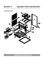
Страница 12: ...8 Model 432 Tim Hortons Operator Parts Identification 150123 Section 4 Operator Parts Identification 432 Exploded View Figure 1...

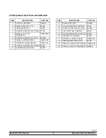
Страница 13: ...OVAL 001086 7 PANEL A UPPER FRONT X66410 SP 8 SPINNER A PANEL MOUNT X82387 27 9 SCREW 10 32X3 8 SLTD TRUSS 24298 10 GASKET BASE PAN 432 052377 ITEM DESCRIPTION PART NO 11 SHELF DRIP TRAY 068600 12 COL...

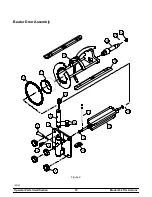
Страница 14: ...10 Model 432 Tim Hortons Operator Parts Identification 150123 Beater Door Assembly Figure 2...

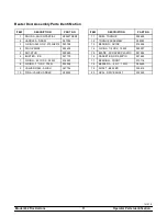
Страница 15: ...T STUD 029880 6 BUSTER ICE 047735 7 O RING 291 OD X 080 W 018550 8 O RING 1 OD X 139 W 032504 9 VALVE DRAW SLUSH 047734 10 PIN A VALVE HANDLE X25929 ITEM DESCRIPTION PART NO 11 ARM TORQUE 052450 12 TO...

Страница 16: ...41219 Accessories Figure 3 ITEM DESCRIPTION PART NO 1 KIT A TUNE UP X50413A 2 BRUSH MIX HOPPER 3 X 7 023316 3 PAIL 10 QT 013163 4 BRUSH DOUBLE ENDED 013072 ITEM DESCRIPTION PART NO 5 BRUSH REAR BEARIN...

Страница 17: ...UTTON SPST 3 DISPLAY LIGHT SWITCH SWITCH TOGGLE SPST 3 4 HP 250V 4 SPINNER INDICATOR LIGHT LIGHT GREEN RECT 125V SPINNER 5 ADD MIX INDICATOR LIGHT LIGHT AMBER RECT 12VDC ADD MIX 6 MIX OUT INDICATOR LI...

Страница 18: ...on the front of the machine above the spinner assemblies The spinner indicator light is activated by pressing the spinner motor switch The light illuminates for 15 seconds indicating the proper blend...

Страница 19: ...parts use an approved food grade lubricant example Taylor Lube MAKE SURE THE POWER SWITCH IS IN THE OFF POSITION Failure to follow this instruction may result in severe personal injury from hazardous...

Страница 20: ...e holes in the blade are securely positioned over the beater pin Figure 8 Step 4 Holding the beater securely slide the beater into the freezing cylinder and align the hole at the rear of the beater wi...

Страница 21: ...tion Figure 11 Step 7 Assemble the freezer door with the Ice Buster door spout clearing device To assemble the door with the ice buster install the o rings on the draw valve and lubricate Figure 12 St...

Страница 22: ...15 Step 11 With the ice buster in place rotate the draw valve to allow installation of the draw handle This will lock the ice buster in place Install the draw handle pin and close the draw valve by mo...

Страница 23: ...onto the four studs on the front of the freezing cylinder Raise the lever that rests on top of the draw valve and push the door into place Install the four handscrews onto the door and tighten them eq...

Страница 24: ...o the freezing cylinder Figure 24 Step 3 While the solution is flowing into the freezing cylinder brush clean the mix hopper and the mix inlet hole Step 4 Place the power switch in the WASH position T...

Страница 25: ...product will be at serving viscosity The viscosity thickness of the slush can be adjusted by turning the viscosity adjustment screw located under the control channel Turn the viscosity adjustment scr...

Страница 26: ...cal health codes DO NOT permit the use of rerun the product must be discarded Follow the instructions in the previous step except drain the product into a pail and properly discard the mix ALWAYS FOLL...

Страница 27: ...the cleaning solution When the solution stops flowing from the door spout move the draw handle to the left and place the power switch in the OFF position Repeat these steps for the other side of the...

Страница 28: ...3 Remove the draw valve ice buster front bearing gasket and prime plug from the freezer door Remove all o rings Note To remove an o ring use a single service towel to grasp the o ring Apply pressure i...

Страница 29: ...h mix in a ratio of 50 50 during the day s operation 5 On a designated day of the week run the mix as low as feasible and discard after closing This will break the rerun cycle and reduce the possibili...

Страница 30: ...ions Disconnect the freezer from the main power source to prevent possible electrical damage Your local Taylor Distributor can perform this service for you Wrap detachable parts of the freezer such as...

Страница 31: ...3 f Unit is unplugged at wall receptacle f Plug in power cord g Tripped circuit breaker or blown fuse g Reset circuit breaker or replace fuse h Beater assembly is rotating counterclockwise h Contact a...

Страница 32: ...6 Scored walls of freezing cylinder a Broken pin on beater assembly a Repair or replace beater assembly b Front bearing worn or missing b Replace or install front bearing 16 7 Excessive leakage into r...

Страница 33: ...2 Drive Shaft O Ring X 2 Scraper Blade X 2 Freezer Door Gasket X 2 Front Bearing X 2 Guide Bearing X 2 Torque Rotor O Ring X 2 Draw Valve O Rings X 4 Brush Mix Hopper 3 x 7 Inspect Replace if Necessar...

Страница 34: ...igeration compressor except service valve Five 5 years Beater motors Two 2 years Beater drive gear Two 2 years Printed circuit boards and Softech controls beginning with serial number H8024200 Two 2 y...

Страница 35: ...ages resulting from the use of any refrigerant other than that specified on the Product s data label will void this limited warranty 13 Any cost to replace refill or dispose of refrigerant including t...

Страница 36: ...rts Twelve 12 months Class 512 Parts Twelve 12 months Class 000 Parts No warranty Taylor Part 072454 Motor 24VDC C832 C842 Four 4 years LIMITED WARRANTY CONDITIONS 1 If the date of original installati...

Страница 37: ...rvice work promptly upon arrival 9 Failure damage or repairs due to faulty installation misapplication abuse no or improper servicing unauthorized alteration or improper operation or use as indicated...

Страница 38: ...FOR LOST SALES LOST PROFITS PRODUCT LOSS PROPERTY DAMAGES OR SERVICE EXPENSES ARE EXPRESSLY EXCLUDED THE EXPRESS WARRANTIES MADE IN THIS LIMITED WARRANTY MAY NOT BE ALTERED ENLARGED OR CHANGED BY ANY...

Страница 39: ...ILTER WHT RIGHT BEATER MOTOR FIG 1 YEL RIGHT BEATER RELAY RIGHT COMPRESSOR RELAY OVERLOAD RELAY WHITE BLK STRIPE 4 A2 2 4 1 CONTACTOR L1 T1 CONTACTOR T2 L2 MTR COMP BLK BLK BLK BLK BLK ORN WHT WHT BLK...

Отзывы: