6-2
OPERATING PROCEDURES
Model 104
Operating Procedures
6
Figure 6-4
4. Holding the beater and blades securely, slide the
beater into the freezing cylinder about one-third of
the way in. Looking into the freezing cylinder, align
the hole at the rear of the beater with the flats on the
end of the driveshaft.
Figure 6-5
5. Slide the beater the remainder of the way into the
freezing cylinder and over the driveshaft. The beater
should fit snugly but not so tightly that the beater
cannot be turned to engage the driveshaft. When in
position, the beater does not protrude beyond the
front of the freezing cylinder.
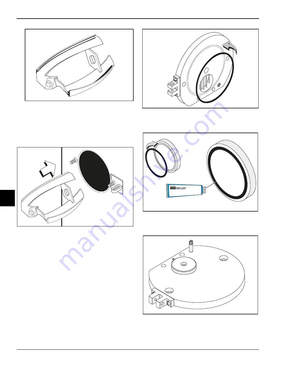
6. Assemble the freezer door. Place the large freezer
door O-ring in the groove on the back of the freezer
door.
Figure 6-6
7. Press the O-ring into the groove on the back of the
freezer door and lubricate
lightly.
Figure 6-7
8. Lay the draw plate and O-ring facedown over the
ejection port.
Figure 6-8
9. Align the hole in the draw arm over the stem on the
freezer door and push down. Make sure the draw
arm fits into the depression in the draw plate.
11084
10138
11085
11086
Apply the appropriate
Taylor approved food safe lubricant.
11087
Содержание 104
Страница 8: ...1 4 TO THE INSTALLER Model 104 To the Installer 1 Notes...
Страница 14: ...3 4 SAFETY Model 104 Safety 3 Notes...
Страница 18: ...4 4 PARTS Model 104 Parts 4 Notes...
Страница 30: ...7 2 OPERATOR CHECKLIST Model 104 Operator Checklist 7 Notes...
Страница 32: ...8 2 TROUBLESHOOTING Model 104 Troubleshooting 8 Notes...
Страница 34: ...9 2 PARTS REPLACEMENT SCHEDULE Model 104 Parts Replacement Schedule 9 Notes...
Страница 40: ...11 4 LIMITED WARRANTY ON PARTS Model 104 Limited Warranty on Parts 11 Notes...


