WEBS-ZPS Zone Paging System Instructions
Copyright © 2011 Talk-A-Phone Co. All rights reserved.
Talk-A-Phone
Co.
• 7530 North Natchez Avenue • Niles, Illinois 60714-3804
Page 2 of 7
Phone 773.539.1100 • Fax 773.539.1241 • [email protected] • www.talkaphone.com
All prices and specifications are subject to change without notice.
Talk-A-Phone, Talk-A-Lert, Scream Alert and WEBS are registered trademarks of Talk-A-Phone Co.
IV. System
Wiring
Option A:
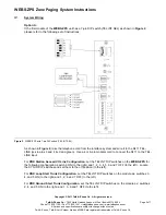
If the first module of the
WEBS-ZPS
unit has a 7-pin DIP switch (TEL INT SEL) as shown in
Figure 2
,
please refer to the following set of instructions:
Figure 2.
WEBS-ZPS with 7-pin DIP switch (TEL INT SEL).
As shown in
Figure 2,
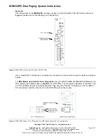
take the telephone cord from the interface system and wire it to the RJ11 TEL-
LINE jack to pins 3 and 4 (red and green). Use a 4 or 6-pin modular cord to connect the RJ11 to the TEL-
LINE input.
For
PBX Station Access/CO Line Configuration
, set the TEL-INT DIP switches on the
WEBS-ZPS
for
the following configuration: switch 6 ON (to the right) and 1, 2, 3, 4, 5, 6 and 7 OFF (to the left). Locate
the SYS-ID DIP switches and set them to the off position (to the left).
For
PBX Loop Start Trunk Configuration
, set the TEL-INT DIP switches on the module as: switches 3,
4, and 5 ON (to the right) and 1, 2, 6 and 7 OFF (to the left).
For
PBX Ground Start Trunk Configuration
, set the TEL-INT DIP switches on the module as: switches
2, 4, and 5 ON (to the right) and 1, 3, 6 and 7 OFF (to the left).


