WEBS-ZPS Zone Paging System Instructions
Copyright © 2011 Talk-A-Phone Co. All rights reserved.
Talk-A-Phone
Co.
• 7530 North Natchez Avenue • Niles, Illinois 60714-3804
Page 4 of 7
Phone 773.539.1100 • Fax 773.539.1241 • [email protected] • www.talkaphone.com
All prices and specifications are subject to change without notice.
Talk-A-Phone, Talk-A-Lert, Scream Alert and WEBS are registered trademarks of Talk-A-Phone Co.
For
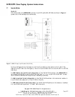
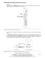
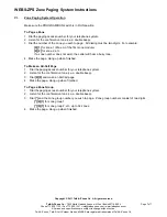
PBX Loop Start Trunk Configuration
, move the TELEPHONE INTERFACE SLIDE switches on the
module to the positions shown in
Figure 5
(i.e. LS and TRUNK). The two center conductors of the RJ11
cord are TIP and RING 48VDC and have a specific polarity. Plug one end of the cord into the Loop Start
Trunk of the PBX and the other end into the TRUNK jack on the module.
Figure 5.
WEBS-ZPS (without 7-pin DIP switch) for a PBX Loop Start Trunk configuration.
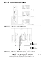
For
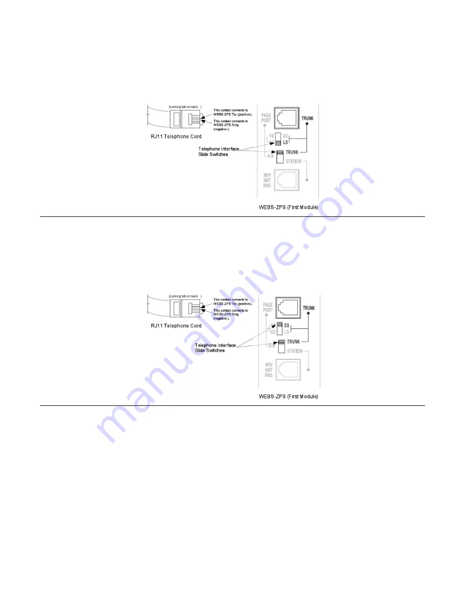
PBX Ground Start Trunk Configuration
, move the TELEPHONE INTERFACE SLIDE switches on
the module to the positions shown in
Figure 6
(i.e. GS and TRUNK). The two center conductors of the
RJ11 cord are TIP and RING 48VDC and have a specific polarity. Plug one end of the cord into the
Ground Start Trunk of the PBX and the other end into the TRUNK jack on the module.
Figure 6.
WEBS-ZPS (without 7-pin DIP switch) for a PBX Ground Start Trunk configuration.
The second module should have all its SYS ID 4-pin DIP switches set to zero. Connect the 12VDC power
supply to the module. Remove the switch lock and place the PROGRAM/RUN switch on the second
module to the RUN position. Set the TALK BACK 3-pin DIP switch to the OFF position (to the left) for all
the zones. Set the OUTPUT switch to LO PWR position.
Locate the terminals labeled ZONE A and connect them to the
WEBS-MT/R
tower. Each
WEBS-MT/R
tower is allocated to a single zone on the
WEBS-ZPS
. Zone A will be Zone 1 and can be paged by
following the directions in
Section VI
of this manual. Zone B will be Zone 2, Zone C will be Zone 3, and
Zone A of the next module will be Zone 4, etc. Follow the same procedure for the remaining zones. Refer
to
Figure 7(a)
or
7(b)
, to connect the
WEBS-ZPS
to the WEBS-MT/R Amplifier (black chassis) or the
WEBS-MT/R Amplifier (silver chassis) respectively.


