Assembly instructions
Assembly
Version 1.0
Rotary indexer TMF
19 / 35
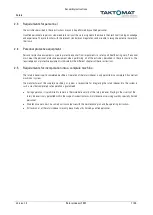
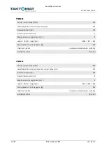
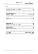
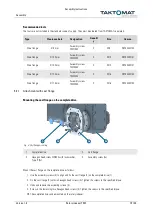
Recommended tools
The tools are not included in the standard scope of supply. They must be ordered from TAKTOMAT separately.
Type
Clearance hole
Designation
Quantit
y
Size
Item no.
Drive flange
Ø 9 mm
Assembly screw
TMF1000
2
M8
ART00332104
Drive flange
Ø 13.5 mm
Assembly screw
TMF2000
2
M12
ART00332101
Drive flange
Ø 13.5 mm
Assembly screw
TMF3000
2
M12
ART00332101
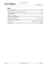
Drive flange
Ø 17.5 mm
Assembly screw
TMF4000
2
M16
ART00332103
Drive flange
Ø 17.5 mm
Assembly screw
TMF5000
2
M16
ART00332103
5.2.1
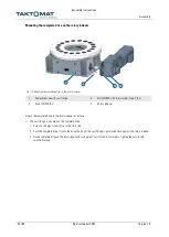
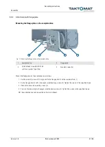
Attachment with cast flange
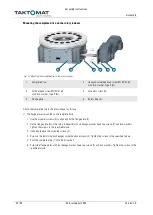
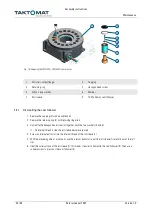
Mounting the cast flange on the complete drive
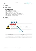
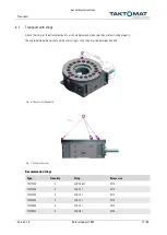
Fig. 9: Cast flange mounting
1
Complete drive
2
Cast flange
3
Hexagon head screw DIN933 with lock washer,
Type S (8x)
4
Assembly screw (2x)
Mount the cast flange on the complete drive as follows:
1.
Use the assembly screws (4) to align and fix the cast flange (2) on the complete drive (1).
2.
Fix the cast flange (2) with six hexagon head screws (3). Tighten the screws to the specified torque.
3.
Undo and remove the assembly screws (4).
4.
Screw in the remaining two hexagon head screws (3). Tighten the screws to the specified torque.
The complete drive can be mounted on the rotary indexer.
4
2
3
1

