


33
Page
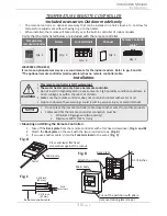
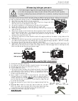
6. Between the
“CHILD-1”
and the
“CHILD-2”
units:
Connect the
“2”
connector of the
“CHILD-1”
unit to the
“1”
connector of the
“CHILD-2”
unit.
7. Between the
“CHILD-2”
and the
“CHILD-3”
units:
Connect the
“2”
connector of the
“CHILD-2”
unit to the
“1”
connector of the
“CHILD-3”
unit.
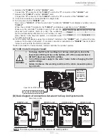
8. Verify that all cables are connected like the diagram (B).
9. Turn on power to the
“PARENT”
unit.
Next,
turn on
“CHILD-1”
. When the controller* installed in
“CHILD-1”
unit displays a number, turn on
“CHILD-2”
.
When the controller* installed in the
“CHILD-2”
unit displays a number, turn on
“CHILD-3”
.
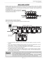
Make sure the controller* installed in each child unit dis-
plays each unit number. (Refer to p. 48.) The numbering
system automatically allocates the unit number to each
water heater in the Easy-Link System, in accordance with
the table on the right.
10. Set the water temperature using the controller* installed in the
“PARENT”
unit. It will set the tem-
perature for the Easy-Link System. If a remote controller is installed to the
“PARENT”
heater of 510 U
Indoor, it will override the built-in controller.
*Built-in controller for indoor models, remote controller for outdoor models.
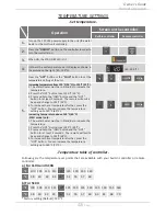
(A) 510U model Computer board
WARNING
•
To change the DIP switch settings for the Easy-Link System, locate the
lower bank of DIP switches at the bottom, left of the computer board.
•
DO NOT adjust any other DIP switches.
•
Turn off the power supply to the water heater before changing the DIP
switch settings.
•
Failure to observe this warning could result in carbon monoxide poison-
ing or death.
Easy-Link /
Multi-Unit
connectors
are next to
the computer
board.
Lower bank of DIP switches
Upper bank of DIP switches
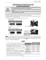
(B) Basic diagram of connections between the Easy-Link System units
NOTE:
The dark square indicates the correct
DIP switch position.
PA
RENT
Communication cable
Lower bank of
DIP switches
OFF
ON
1
1
1
1
2
2
2
2
PA
RENT
PA
RENT
PA
RENT
1
2
3
4
5
6
1
2
3
4
5
6
OFF
ON
OFF
ON
1
2
3
4
5
6
OFF
ON
1
2
3
4
5
6
Lower bank of
DIP switches
Lower bank of
DIP switches
Lower bank of
DIP switches
Connectors
Connectors
Connectors
Connectors
PARENT unit
CHILD-1 unit
CHILD-3 unit
CHILD-2 unit
Remote controller
Installation
Installation Manual
Type of unit
Unit # of easy-link
Parent
1
Child
2, 3, or 4