


13
Page
VENTING INSTRUCTIONS
For indoor models
-General-
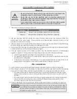
WARNING
•
Improper venting of this appliance can result in excessive levels of carbon
monoxide which can result in severe personal injury or death.
•
Improper installation can cause nausea or asphyxiation, severe injury or death
from carbon monoxide and flue gases poisoning. Improper installation will void
product warranty.
•
When installing the vent system, all applicable national and local codes must be
followed. If you install thimbles, fire stops or other protective devices and they
penetrate any combustible or noncombustible construction, be sure to follow
all applicable national and local codes.
The water heater must be vented in accordance with “Venting of Equipment" in the current edition of the
National Fuel Gas Code: ANSI Z223.1/NFPA 54, as well as applicable local building codes.
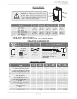
The manufacturer recommends NovaVENT™ or Z-Vent® category III, single wall, stainless steel venting.
See "Approved Category III, Single Wall, Stainless Steel Venting Suppliers and Part Numbers" on page 14.
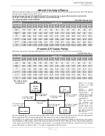
General rules for air intake:
The water heater can obtain its combustion air from the space that it is installed in or it can be direct
vented.
•
The air intake can use 3" PVC (solid core), CPVC (solid core), ABS, or category III vent.
•
Use of cellular core PVC (ASTM F891), cellular core CPVC, or Radel® (polyphenylsulfone) in non-
metallic venting systems is prohibited. Covering non-metallic vent pipe and fittings with thermal
insulation is prohibited.
•
Ensure that the installation location has sufficient, clean combustion air. If unsure, direct vent the
heater or refer to the Combustion Air Supply section below.
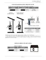
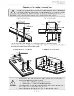
Direct venting installation:
•
The maximum length of intake air piping must not exceed 60 ft (18.3 m). Deduct 5 ft (1.5 m) for
each 90° elbow or 2.5 ft (0.76 m) for each 45° elbow used in the venting system. Two 45° elbows
when connected together are equivalent to one 90° elbow. Refer to the tables on p. 19.
•
When the horizontal air intake exceeds more then 5 ft, support the pipe every 3 ft with pipe hang-
ers.
•
Vertical air intake pipe must be supported with pipe hangers. Ensure that the weight of the pipe
is not carried by the water heater.
Combustion air from the room:
•
Install a 3" elbow into the air intake collar.
General rules for venting water heaters are:
•
Place the water heater as close as possible to the vent termination.
•
The vent collar of the water heater must be fastened directly to an unobstructed vent pipe.
•
Do not weld the vent pipe to the water heater’s vent collar.
•
Do not cut or alter the shape of the vent collar of the unit.
•
The vent must be easily removable from the top of the water heater for normal service and
inspection of the unit and vent system.
•
The water heater vent must not be connected to any other gas appliance or vent stack.
•
Avoid using an oversized vent pipe or using extremely long runs of pipe.
•
For rooftop venting, a rain cap or other form of termination that prevents rain water from
entering into the water heater must be installed.
•
Do not common vent or connect any vent from other appliances to the water heater vent.
Installation
Installation Manual