


21
Page
Installation
Installation Manual
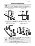
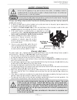
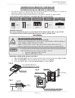
Two-Pipe, Direct-Vent Installation Examples
Vertical
condensation
drain**
Horizontal Installation
Wall
Hanger
Hanger
Sidewall vent
termination
Backflow
preventer*
Fire stop
Vertical Installation
Vertical
condensation drain**
Backflow
preventer*
Rain cap
Roof flashing
Hanger
Wall
Direct-vent
concentric
termination
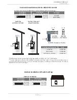
Horizontal Installation with
direct-vent concentric termination
(Refer to p.10)
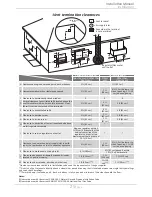
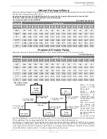
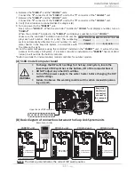
110U Indoor
310U Indoor
510U Indoor
(Upper bank of DIP switches)
Vent length
No. 6 : O N
No. 7 : OFF
No. 8 : OFF
No. 3 : O N
No. 4 : OFF
No. 5 : OFF
0 to 20 ft
(0 to 6.1 m)
No. 6 : OFF
No. 7 : OFF
No. 8 : OFF
No. 3 : OFF
No. 4 : OFF
No. 5 : OFF
21 to 40 ft
(DEFAULT)
(6.2 to 12.2 m)
No. 6 : O N
No. 7 : O N
No. 8 : OFF
No. 3 : ON
No. 4 : ON
No. 5 : OFF
41 to 60 ft
(12.3 to 18.3 m)
OFF
ON 1 2 3 4 5 6 7 8 9 10
OFF
ON 1 2 3 4 5 6 7 8
OFF
ON 1 2 3 4 5 6 7 8 9 10
OFF
ON 1 2 3 4 5 6 7 8
OFF
ON 1 2 3 4 5 6 7 8 9 10
OFF
ON 1 2 3 4 5 6 7 8
DIP switch settings for direct vent installation
*Backflow preventer (Recommended for freezing weather
conditions: 36 °F (2 °C) and below).
**Vertical condensation drain must be installed in accordance with
local codes. It is
required to be installed in the venting system when there
is more than 5 ft (1.5 m) of equivalent vent length, not including the sidewall
termination. 90° elbow is equivalent to 5 ft (1.5 m) of vent length.
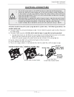
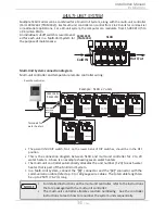
Direct-vent sidewall Installation
(Refer to p.23)
1 ft (305 mm)
min.
0.4 ft
(130 mm)
min.
0.4 ft
(130 mm)
min.
Exhaust
Intake
Exhaust
Intake