background image

CHAPTER 4 SYSTEM MENU OPERATION 


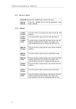
4.1.8  PROFILE submenu tree  


Use a 

PROFILE

 from the manufacturer.  For quick configuration steps, it 

may be helpful and will assist the user to maintain the system as well.  The 

sub-menu tree of the 

PROFILE

 is shown in Table 4-6 


Table 4-6 : The 

PROFILE

 submenu items 

PROFILE  

Description: 

Configuration Profile Setting 

Options: 

0-CO-2048-INT 


CO Site, 2048 KBPS, internal clock 

1-CP-2048-RCV  CPE Site, 2048 KBPS, receive clock 
2-CO-2048-DTE  CO Site, 2048 KBPS, DTE clock 
3-CO-E1-UF-DTE CO Site, E1, DTE clock 
4-CP-E1-UF-RCV  CPE Site, E1, receive clock 
5-CO-E1-FR-DTE  CO Site, E1, DTE clock, Frame CRC4 
6-CP-E1-FR-RCV  CPE Site, E1, receive clock, Frame CRC4 
7-NTU-E1-UF-RCV  NTU, E1, receive clock, Unframed   
8-NTU-E1-FR-RCV NTU, 

E1, 

receive clock, frame CRC4  

9-NTU-2048-RCV 

NTU, 2048 KBPS, receive clock 


Break time 

37 

Содержание Xstream 1300 Series

Страница 1: ...COMMUNICATION SYSTEM CORP Headquarters No 25 Alley 15 Lane 120 Sec 1 Nei Hu Rd Taipei 114 Taiwan TEL 886 2 26583000 FAX 886 2 26583232 Beijing Branch 3F A Building 113 Zhi Chun Lu HaiDian District Bei...

Страница 2: ......

Страница 3: ...he separation between the equipment and receiver Connect the equipment into an outlet on a circuit different from that to which the receiver is connected Consult the dealer or an experienced radio TV...

Страница 4: ...names mentioned in this manual are used for identification purposes only and may be trademarks or trademarks of their respective companies The information provided from Tainet Communication System Cor...

Страница 5: ...entatives HQ No 25 Alley 15 Lane 120 Sec 1 N e is H u Rd Taipei Taiwan R O C TEL 886 2 2658 3000 E mail sales tainet net FAX 886 2 2658 3232 URL http www tainet net Beijing Branch 3F A Building 113 Zh...

Страница 6: ......

Страница 7: ...INSTALLATION GUIDE 17 3 1 Unpacking 18 3 2 Preliminary Preparations 19 3 3 Set up Procedures 19 3 4 Configuration Procedures 20 3 4 1 Load Factory Profile 20 3 5 Trouble Report 22 CHAPTER 4 SYSTEM MEN...

Страница 8: ...p 50 6 3 3 PPP Setup 50 6 3 4 FrRelay Setup 51 6 3 5 AUX Setup 51 6 3 6 Routing Table 51 6 3 7 Device Control 52 6 3 8 Monitor 52 6 4 How to Operate and Setup Internet Applications 53 6 5 How to Opera...

Страница 9: ...oop back 66 APPENDIX E FACTORY PROFILES 67 APPENDIX F SOFTWARE UPGRADE 69 F 1 Overview 69 F 2 Craft Port Download 69 F 3 Procedures 69 F 4 FLASH Download 70 APPENDIX G TROUBLE REPORT 71 APPENDIX H GLO...

Страница 10: ...5 for V 35 and RS 530 interface 16 Figure 2 9 Router Module 16 Figure 3 1 Network structure 19 Figure 4 1 System Menu 25 Figure 5 1 The Craft Port Connection to PCs or Terminals COM Port 41 Figure 5 2...

Страница 11: ...33 Table 4 5 The STATUS submenu items 35 Table 4 6 The PROFILE submenu items 37 Table B 1 V 35 Cable pin definition 61 Table C 2 RS 530 Connector pin definition 62 Table C 3 V 36 RS 449 Cable pin defi...

Страница 12: ......

Страница 13: ...APTER 1 INSIDE THE XSTREAM 1300 CHAPTER 1 INSIDE THE XSTREAM 1300 Overview 1 1 Description 1 2 Features 1 3 Specifications 1 4 Applications 1 4 1 Cellular network 1 4 2 Campus network 1 4 3 E1 network...

Страница 14: ...er loop distance capability will reduce the cost and effort required for repeater installation compared to traditional T1 E1 or fractional T1 E1 services To provide maximum distance the XSTREAM 1300 c...

Страница 15: ...hnologies Carrying symmetrical 2048 Kbps payload for up to 3 2 miles 5 18Km over 24 AWG single pair copper wire Multi Line Rate support including 144K 272K 400K 528K 784K 1040K for Xstream 1310 1330 M...

Страница 16: ...30 meters 768 Kbps 23 000 feet 7 000 meters 1024 Kbps 20 000 feet 6 100 meters 1536 Kbps 18 000 feet 5 490 meters 2048 Kbps 17 000 feet 5 180 meters 2304 Kbps 16 000 feet 4 880 meters Clock source CO...

Страница 17: ...t status indicator Craft port 2400 19200 38400 BPS 8 bit data length None parity 1 stop bit 9 pin D sub female connector Power Source Input 110 220 Vac 10 36 72 Vdc Power Consumption 10 W Sealing Curr...

Страница 18: ...ell sites to mobile telephone switching offices MTSOs Tainet s XSTREAM 1300 provides an alternative to standard repeater E1 service Figure 1 1 shows a cellular network application Figure 1 1 Cellular...

Страница 19: ...pment CPE unit Each XSTREAM 1300 is configured at the factory to operate at the CO side of an E1 connection However you can easily modify CO setting for CPE site unit Figure 1 2 Campus network applica...

Страница 20: ...eater in the E1 network and effectively doubling the utilization of the existing twisted copper pair Figure 1 4 shows a general E1 network Figure 1 4 E1 application of the XSTREAM 1300 with G 703 I F...

Страница 21: ...CHAPTER 2 INTERFACING CHAPTER 2 INTERFACING Overview 2 1 Front Panel 2 1 1 LCD Display 2 1 2 Top Menu 2 1 3 Status Indicators 2 1 4 Keypad 2 2 Rear panel 9...

Страница 22: ...L DTE1 DTE2 SQ ALM TST LCD Display Status Indicators Keypad 1300 Figure 2 1 Front panel of the XSTREAM 1300 User can operate the XSTREAM 1300 from the front panel The following functions can be perfor...

Страница 23: ...rations Figure 2 2 shows the LCD display XSTREAM L 2048 Kbps CO connected 42I 1300 1300 Figure 2 2 The LCD Display 2 1 2 Top Menu When the XSTREAM 1300 has finished the initialization The LCD display...

Страница 24: ...Idle status handshaking Handshaking training In training linked The DSL link has been created sync hunting Synchronous word is hunting connected In data mode local loopb In local loop back test mode d...

Страница 25: ...rt 1 Exist DTE2 DTE Port 2 Green Unequipped or Failure N A N A DTE Port 2 Exist SQ Signal Quality Red No Error CRC Error Occurring N A Loop Open ALM Alarm Event Red N A N A N A Disconnection TST Testi...

Страница 26: ...menu Go to down layer menu or decide item Move to right menu Move to left menu item Return to top menu Switch menu operation to remote or local If user selects REM LOC keypad after connection this wi...

Страница 27: ...0 s power switch 2 AC Receptacle AC plug for power cord 3 Ground Terminal Ground output terminal connect to earth 4 DSL jack RJ 45 jack for DSL link 5 Craft Interface 9 pin female serial D sub connect...

Страница 28: ...TER 2 INTERFACING Figure 2 6 Terminal block for G 703 E1 balanced interface Figure 2 7 BNC for G 703 unbalanced interface Figure 2 8 DB 25 for V 35 and RS 530 interface 1 8 1 8 Figure 2 9 Router Modul...

Страница 29: ...CHAPTER 3 INSTALLATION GUIDE Overview 3 1 Unpacking 3 2 Preliminary Preparations 3 3 Set up Procedures 3 4 Configuration Procedures 3 4 1 Load Factory Profile 3 4 2 Local Loop back Test 3 4 3 Make Con...

Страница 30: ...Balanced module G 703 E1 Unbalanced interface A G 703 E1 Unbalanced module ITU T V 35 Nx64Kbps interface V 35 module V 35 cable EIA RS 530 Nx64Kbps interface RS 530 module 10BaseT interface Router mod...

Страница 31: ...o XSTREAM 1300 5 Connect test cable to the DTE interface of XSTREAM 1300 and the BER tester User can also use a terminal emulation program to configure the XSTREAM 1300 Configure terminal for 19200 BP...

Страница 32: ...ile Local Loop back Test and Make Connection 3 4 1 Load Factory Profile 1 Switch on the XSTREAM 1300 and wait until LCD s screen shows as top indicated 2 Press DOWN LEFT DOWN DOWN keys in sequence as...

Страница 33: ...Press DOWN RIGHT 3 times DOWN RIGHT DOWN key and the LCD s screen to show L 2048 Kbps CO handshaking I L MENU SELECT STATUS L MENU SELECT TEST CONFIG L TEST CONFIG CLOSE ALL L TEST CONFIG LL TEST L T...

Страница 34: ...rt L PROFILE 0 CO 2048 INT 3 Wait for several seconds both XSTREAM 1300 will perform CONNECTING test mode L 2048 Kbps CO connected 42I L 2048 Kbps CPE connected 42R 4 Make sure both BER testers are co...

Страница 35: ...MENU OPERATION Overview 4 1 Main Menu 4 1 1 Submenu Tree 4 1 2 The Configuration of the XSTREAM 1300 4 1 3 MODEM CONFIG submenu tree 4 1 4 DTE CONFIG submenu tree 4 1 5 TEST CONFIG submenu tree 4 1 7...

Страница 36: ...o down layer menu or decide item Move to right menu Move to left menu item Return to top menu Switch menu operation to remote or local Figure 4 1 shows display screens from switch on until completed T...

Страница 37: ...CHAPTER 4 SYSTEM MENU OPERATION Figure 4 1 System Menu 25...

Страница 38: ...are Please call the local representative to help in upgrading the 4 1 2 The Configuration of the XSTREAM 1300 The configuration can be modified and saved by the user The XSTREAM 1300 starts up with it...

Страница 39: ...k does not perform correctly The sub menu tree of the MODEM CONFIG of the XSTREAM 1300 is shown in the Table 4 2 Table 4 2 The MODEM CONFIG submenu items MODEM CONFIG MODE Description Indicates the pl...

Страница 40: ...RISING EDGE Description DTE Transmit Data Signal Stage Options NORMAL Framer sets up automatically FALLING EDGE Force DTE transmit data is clocked at falling edge RISING EDGE Force DTE transmit data...

Страница 41: ...Table 4 3 The DTE CONFIG submenu items DTE CONFIG SPEED Description Set up the Speed of the XSTREAM 1300 Options 64 KBPS 1 x 64 KBPS 128 KBPS 2 x 64 KBPS 1040 KBPS 16 x 64 KBPS 1552 KBPS 24 x 64 KBPS...

Страница 42: ...cription Data Port Selection Options DTE 1 Use the data port 1 DTE1 DTE 2 Use the data port 2 DTE2 RTS SIGNAL V 35 RS 530 Description Request to Send Options NORMAL Detects the DTE interface RTS signa...

Страница 43: ...xD signal to follow the ExC signal Normally the RxD signal follows the RxC signal Options FOLLOW RxC Force the RxD signal to follow RxC signal FOLLOW ExC Force the RxD signal to follow ExC signal FOLL...

Страница 44: ...Description Specify turning on period the LCD backlight Options OFF Always off ON 3 MIN Turn off after last key press 5 minutes later ALWAYS ON Always on KEY TONES Description Turn the key tones on or...

Страница 45: ...e loop back functions include the following LL TEST Local Loop back Test DL TEST Digital Loop back Test DTE1 LOOPBACK DTE1 Loop back Test The TEST CONFIG submenu tree is shown in the Table 4 4 Table 4...

Страница 46: ...MIN Shows the current 15 minutes Error status E1 15 MIN REPORT Shows the Report in past 15 minutes E1 DAILY REPORT Shows the daily Report CLEAR ALL Clear all report and counter in E1 PM MDSL P M MDSL...

Страница 47: ...e unit is dB TX POWER Description Transmitted Power the unit is dBm RCV GAIN Description Receiver Gain the unit is dB LINE Description Loop Distance Detection The item is only available when the XSTRE...

Страница 48: ...ce exist but unknown type DTE2 Description DTE 2 port interface type Probabilities NOT EQUIPPED No DTE equipped V 35 V 35 interface RS 530 RS 530 interface EXIST DTE interface exist but unknown type A...

Страница 49: ...tion Configuration Profile Setting Options 0 CO 2048 INT CO Site 2048 KBPS internal clock 1 CP 2048 RCV CPE Site 2048 KBPS receive clock 2 CO 2048 DTE CO Site 2048 KBPS DTE clock 3 CO E1 UF DTE CO Sit...

Страница 50: ......

Страница 51: ...INAL OPERATION CHAPTER 5 SYSTEM TERMINAL OPERATION Overview 5 1 Overview 5 2 Connection 5 3 Keyboard 5 4 Pop Up Boxes 5 5 Procedures 5 6 SYSTEM CONFIGURATION submenu 5 7 DISPLAY STATUS submenu 5 8 LOA...

Страница 52: ...emulation program to set up the XSTREAM 1300 via craft port 5 2 Connection The craft port operation of the XSTREAM 1300 is similar to a normal PC To view the whole operation user can utilize a PC mon...

Страница 53: ...the XSTREAM 1300 via the Craft Port 5 5 Procedures 1 Make sure that PCs or Terminals of the COM port setting are set to At least 9600 baud rate 8 bit characters No parity 1 stop bit Hardware flow con...

Страница 54: ...5 pin one the user can change the adapter through correct pin assignments 4 The main menu screen will display on the PC s or Terminal s Monitor if the connection is successful See Figure 5 2 5 If ther...

Страница 55: ...e next pop up menu will come up as Figure 5 3 It is clear that the System Configuration has come up with six options to be chosen by the user The first three options 1 3 MODE Tx Pwr ATTENUATION and WE...

Страница 56: ...ystem status and parameters via the DISPLAY STATUS The basic Pop Up menu can be found in the Figure 5 4 Figure 5 4 Pop Up Menu of the DISPLAY STATUS The DISPLAY STATUS of the XSTREAM 1300 provides som...

Страница 57: ...APTER 5 SYSTEM TERMINAL OPERATION 5 8 LOAD PROFILE submenu If user has difficulty in configuring the XSTREAM 1300 they can make use of the Load Profile menu Figure 5 5 Pop Up Menu of the Load Profile...

Страница 58: ......

Страница 59: ...CD Menu Tree 6 3 The Description of the Configuration 6 3 1 LAN Setup 6 3 2 WAN Setup 6 3 3 PPP Setup 6 3 4 FrRelay Setup 6 3 5 AUX Setup 6 3 6 Routing Table 6 3 7 Device Control 6 3 8 Monitor 6 4 How...

Страница 60: ...dule will appear on the Main Menu Following is the illustration of Router Module To install the router module onto Xstream 1300 unscrew the cover and firmly install the router module to DTE1 interface...

Страница 61: ...Async 1200 Enter to confirm Enter to confirm Warm Start Ddfault Gateway Restore Default LAN Rx Packets LAN Tx Packets LAN Rx Errors Routing Table Device Control Monitor WAN Rx Packets WAN Tx Packets W...

Страница 62: ...notation is used in conjunction with an IP address to specify which bits of the address make up the network part and which the host part A one 1 in a mask bit location means the corresponding bit in t...

Страница 63: ...entifier the Data Link Connection Identifier address for the connection 6 3 5 AUX Setup AUX Port Enable or Disable the AUX port Local IP This parameter identifies the IP address for local WAN port whe...

Страница 64: ...ket unknown or unsupported protocol etc WAN Rx Packets The total number of input packets received from the WAN interface WAN Tx Packets The total number of packets sent to the WAN interface WAN Rx Err...

Страница 65: ...der LAN Setup menu IP Address 192 10 25 1 Step 2 Under LAN Setup menu IP NetMask 255 255 255 0 Step 3 Under WAN Setup menu WAN Protocol PPP Step 4 Under PPP Setup menu Local Address 192 72 240 252 Ste...

Страница 66: ...2 Under LAN Setup menu IP NetMask 255 255 255 0 Step 3 Under WAN Setup menu WAN Protocol Frame Relay Step 4 Under FrRelay Setup menu Local Address 192 72 240 252 Step 5 Under FrRelay Setup menu IP Net...

Страница 67: ...1 Setup Step 1 Under LAN Setup menu IP Address 192 72 244 1 Step 2 Under LAN Setup menu IP NetMask 255 255 255 0 Step 3 Under WAN Setup menu WAN Protocol PPP Step 4 Under PPP Setup menu Local Address...

Страница 68: ...WAN Setup menu WAN Protocol PPP Step 4 Under PPP Setup menu Local Address 192 72 243 1 Step 5 Under PPP Setup menu IP NetMask 255 255 255 255 Step 6 Under PPP Setup menu WAN Port Speed Sync External...

Страница 69: ...1 V 35 Interface C 2 RS 530 Interface C 3 V 36 RS 449 Interface C 4 X 21 Interface C 5 DB 9 Interface C 6 RJ 45 Interface Appendix D Loopback D 1 Local Loop back D 2 Digital Loop back Appendix E Fact...

Страница 70: ...IP 3 DIP 4 G703B 3L ON ON ON ON G 703 Module G703U 3L ON ON ON ON Router Module Router L OFF ON ON ON Reserve DTE 1 No Equipped OFF OFF OFF OFF ON ON ON ON Reserved OFF ON ON ON G 703 Module Prelimina...

Страница 71: ...N 1 32 with FIFO Female with adaptor cable Model Name Part No Description 1300T 000075 0013 MSDSL Up to 2M Standalone Basic Unit without DTE I F module Up to two DTE I F are supported Outdoor 1300DT M...

Страница 72: ...I F Nx64 KBPS N 1 16 with FIFO Female with adaptor cable Model Name Part No Description TRS 32 000053 0004 Shelf for IDSL MDSL HDSL MSDSL series 19 Rack Mounted chassis with 50 pin centronic connecto...

Страница 73: ...to Send D DCE 6 Data Set Ready E DCE 8 Data Carrier Detect F DCE 20 Data Terminal Ready H DTE 2 Transmit Data A P DTE 3 Receive Data A R DCE 14 Transmit Data B S DTE 16 Receive Data B T DCE 24 Termin...

Страница 74: ...ctor A DCE 9 Receive Signal Element Timing B DCE 10 Receive line Signal Detector B DCE 11 EXT Transmit Signal Element Timing B DTE 12 Transmit Signal Element Timing B DCE 13 Clear to Send B DCE 14 Tra...

Страница 75: ...r to Send A 9 DCE 6 Data Mode A 11 DCE 20 Terminal ready A 12 DTE 8 Receive Ready A 13 DCE 24 Terminal Timing A 17 DTE 7 Signal Ground 19 20 37 Common 14 Send Data B 22 DTE 12 Send Timing B 23 DCE 16...

Страница 76: ...CTRL a 4 8 RXD a 5 17 Indication 6 24 RXC a 7 7 Signal Ground 8 14 TXD b 9 19 CTRL b 10 16 RXD b 11 10 Indication 12 9 RXC b 13 11 EXC b 14 G G Figure C 6 DB 25M Interface Figure C 7 DB 37F Interface...

Страница 77: ...RJ 45 Connector pin definition RJ 45 10BaseT Signal 1 TxD Twist Pair 2 TxD Twist Pair 3 RxD Twist Pair 6 RxD Twist Pair Table C 8 AUX port RJ 45 Connector pin definition RJ 45 AUX port description 1...

Страница 78: ...l Loop back DTE I F LOCAL MSDSL SYSTEM MSDSL DATA PUMP X Figure D 1 Local loop back D 2 Digital Loop back DTE I F LOCAL MSDSL SYSTEM MSDSL DATA PUMP REMOTE MSDSL SYSTEM MSDSL DATA PUMP DTE I F X X DSL...

Страница 79: ...2048 DTE SPEED 2048 KBPS 2048 KBPS 2048 KBPS TX CLOCK INTERNAL CLOCK RECEIVER CLOCK DTE CLOCK RATE ADAPTION FOLLOW SET UP FOLLOW SET UP FOLLOW SET UP DTE PORT DTE 2 DTE 2 DTE 2 RTS SIGNAL NORMAL NORMA...

Страница 80: ...KBPS 2048 KBPS 2048 KBPS 2048 KBPS TX CLOCK DTE CLOCK RECEIVER CLOCK DTE CLOCK RECEIVER CLOCK RATE ADAPTION FOLLOW SET UP FOLLOW SET UP FOLLOW SET UP FOLLOW SET UP DTE PORT DTE 1 DTE 1 DTE 1 DTE 1 RTS...

Страница 81: ...t Download The Craft Port could assist the system software upgrade function for a standalone termination unit like Tainet s XSTREAM 1300 The PCs or terminals with COM port could be connected to the XS...

Страница 82: ...LCD will displays FLASH ERASING 8 The XSTREAM 1300 FLASH memory dumps will display on the PC s or Terminal s Monitor if the connection is successful 9 When C character is present send the binary file...

Страница 83: ...ort Company Local Representation Purchase Order No Equipment Serial No Software Version Please describe 1 Testing Network Structure 2 Configuration 3 Testing Network Equipment 4 Trouble Description E...

Страница 84: ...APPENDIX TAINET COMMUNICATION SYSTEM CORP FAX 886 2 2658 3232 E MAIL sales tainet net 72...

Страница 85: ...Panel 2 2 Clock source 1 4 H Configuration Procedure 3 4 HOME 2 5 4 3 Copyright ii Humidity 1 5 CPE 1 5 2 4 I Craft port 5 CRAFT SPEED 4 10 INTERFACING 2 1 CTS SIGNAL 4 8 K D KEY TONES 4 10 DB9 Connec...

Страница 86: ...onnector A 9 A 10 ROUTER 6 1 RS 530 Connector A 6 RTS SIGNAL 4 8 S S N 4 12 Sealing Current 1 5 SERVICE iv Setup Procedures 3 3 Specification 1 4 SQ 1 5 2 4 STATUS 4 4 4 12 Status Indicator 1 5 Status...

Отзывы: