Table of figures
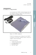
Figure 1-1: COMET components ...........................................................3
Figure 2-1: Installing the battery ............................................................9
Figure 2-2: Opening the COMET display ............................................10
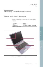
Figure 2-3: COMET components .........................................................11
Figure 2-4: COMET front panel ...........................................................12
Figure 2-5: COMET right side .............................................................12
Figure 2-6: COMET back panel ...........................................................13
Figure 2-7: COMET left side................................................................14
Figure 2-8: Bottom of COMET ............................................................15
Figure 2-9: COMET power switch .......................................................16
Figure 3-1: Opening the display cover .................................................20
Figure 3-2: AC adapter connector.........................................................22
Figure 3-3: Installing the battery ..........................................................24
Figure 3-4: Removing the battery.........................................................25
Figure 3-5: Cover for the expansion battery connector bay.................26
Figure 3-6: Expansion battery connector exposed ...............................26
Figure 3-7: Expansion battery lock in the open position .....................27
Figure 3-8: Expansion battery aligned in place ....................................28
Figure 3-9: Expansion battery locked in place .....................................29
Figure 3-10: Smart Card slot ................................................................35
Figure 3-11: Inserting a Smart Card .....................................................36
Figure 3-12: Removing a Smart Card...................................................37
Figure 3-13: Right side USB ports .......................................................39
Figure 3-14: Back panel USB port .......................................................39
Figure 3-15: RJ-45 Ethernet port..........................................................40
Figure 3-16: Integrated keyboard layout ..............................................42
Figure 3-17: The Touch Pad .................................................................52
Figure 3-18: External monitor port.......................................................55
Figure 3-19: USB ports.........................................................................55
Figure 3-20: LEDs on lower portion of the display .............................58
Figure 3-21: LEDs on the top of the keyboard.....................................59
xx
COMET User’s Guide
Preface
Table of figures
Содержание COMET12
Страница 1: ...COMET12 User s Guide...
Страница 17: ...Preface...
Страница 23: ...Chapter 1 Overview...
Страница 28: ...this page blank 6 COMET User s Guide...
Страница 29: ...Chapter 2 Getting Started...
Страница 39: ...Chapter 3 Using COMET...
Страница 82: ...this page blank 60 COMET User s Guide...
Страница 83: ...Chapter 4 Configuring COMET...
Страница 105: ...Chapter 5 Maintaining COMET...
Страница 114: ...92 COMET User s Guide this page blank...
Страница 115: ...Chapter 6 COMET Specifications...
Страница 118: ...96 COMET User s Guide this page blank...
Страница 119: ...Index...
Страница 122: ...Index 100 COMET User s Guide...


