9100A/9200A/9400
Maintenance and Performance Checks 3-11
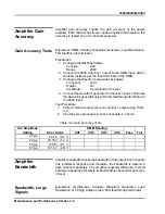
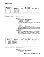
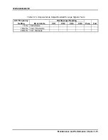
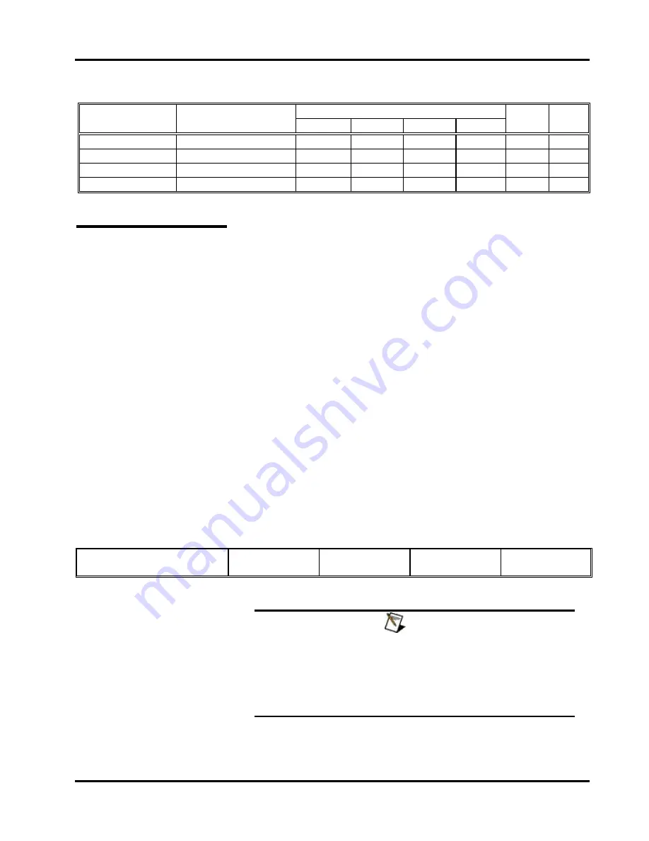
Table
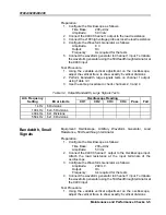
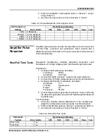
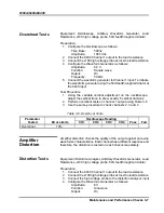
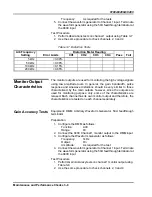
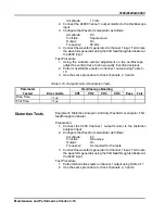
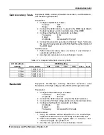
3-11, Output Monitor Distortion Tests
Arb Frequency
Distortion Meter Reading
Setting Error
Limits
CH1
CH2
CH3
CH4
Pass
Fail
1 kHz
<0.08%
50 kHz
<0.08%
100 kHz
<0.15%
200 kHz
<0.65%
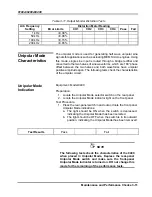
Unipolar Mode
Characteristics
The unipolar mode is used for generating half wave unipolar sine
signals for applications such as actuating MEMS micro engines. Using
this mode, single sine input is routed through a bridge rectifier and
converted to the two halves of sine waveforms, which are 180
°
phase
offset between the two halves and both waveforms have unipolar
positive amplitude span. The following tests check the characteristics
of the unipolar circuit.
Unipolar Mode
Indication
Equipment
:
Model 9400
Preparation:
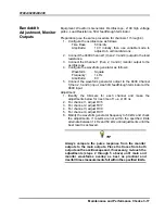
1. Locate the Unipolar Mode selector switch on the rear panel
2. Locate the Unipolar Mode indicator light on the front panel
Test Procedure
1. Press the rear-panel switch in and out and note the front panel
Unipolar Mode indications:
a. The light should be ON when the switch is depressed,
indicating the Unipolar Model has been selected
b. The light should be OFF when the switch is in its outward
position, indicating the Unipolar Model has been removed
Test Results
Pass
Fail
NOTE
The following tests check the characteristics of the 9400
when placed in Unipolar Mode. Depress the rear-panel
Unipolar Mode switch and make sure the front-panel
Unipolar Mode indicator is turned on. DO not change this
mode for the remaining of the performance tests.
Содержание 9100A
Страница 8: ...iv This page intentionally left blank...
Страница 14: ...9100A 9200A 9400 1 6 Installation Figure 1 1 Dual Rack Mounting Option...
Страница 28: ...9100A 9200A 9400 2 14 Introduction and Operating Instructions This page was intentionally left blank...
Страница 46: ...9100A 9200A 9400 Maintenance and Performance Checks 3 18...

