9100A/9200A/9400
Maintenance and Performance Checks 3-6
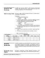
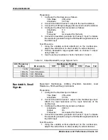
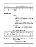
2. Perform bandwidth, small signals tests on channel 1 output
using Table 3-4
3. Use the same procedure to check channels 2, 3 and 4
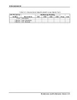
Table
3-4, Output Bandwidth, Small Signals Tests
Arb Frequency
Oscilloscope Reading
Setting Error
Limits
CH1
CH2
CH3
CH4
Pass
Fail
1 kHz
6 Divisions
500 kHz
6 ±0.5 Divisions
1 MHz
6 ±1.8 Divisions
1.8 MHz
6 ±1.8 Divisions
Amplifier Pulse
Response
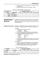
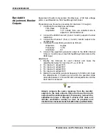
Amplifier pulse response checks the aberrations, which include rise
and fall times, overshoot and undershoot. Each channel has a
different response and therefore, the pulse response is tested on each
channel separately.
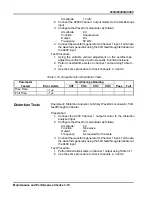
Rise/Fall Time Tests
Equipment
:
Oscilloscope, Arbitrary Waveform Generator, Load
Resistance, x100 high voltage probe, 50
Ω
feedthrough terminator
Preparation:
1. Configure the Oscilloscope as follows:
Time Base:
500ns
Amplitude: 100
V/div
2. Connect the 9400 Channel 1 output to the load resistance
3. Connect the x100 high voltage probe across the load resistance
4. Configure the Waveform Generator as follows:
Amplitude:
8 V
Function:
Square wave
Output: On
Frequency: 50
kHz
5. Connect the waveform generator to Channel 1 input. Terminate
the waveform generator using the 50
Ω
feedthrough terminator at
the 9400 input
Test Procedure
1. Using the variable vertical adjustment on the oscilloscope,
adjust the vertical trace to show exactly 6 vertical divisions
2. Perform rise/fall time tests on channel 1 output using Table 3-5
3. Use the same procedure to check channels 2, 3 and 4
Table
3-5, Rise/Fall Time Tests
Parameter
Oscilloscope
Reading
Tested Error
Limits
CH1
CH2
CH3
CH4
Pass
Fail
Rise Time
<1
μ
s
Fall Time
<1
μ
s
Содержание 9100A
Страница 8: ...iv This page intentionally left blank...
Страница 14: ...9100A 9200A 9400 1 6 Installation Figure 1 1 Dual Rack Mounting Option...
Страница 28: ...9100A 9200A 9400 2 14 Introduction and Operating Instructions This page was intentionally left blank...
Страница 46: ...9100A 9200A 9400 Maintenance and Performance Checks 3 18...

