background image

DSC Q Series Getting Started Guide


14

DSC System Components

A functional DSC system has three major components:  the instrument itself, which contains the system 
electronics; the cell, which monitors differential heat flow and temperature; and a cooling accessory.  The cooling 
accessory selected depends on the temperature range desired for your experiments.

DSC Cell

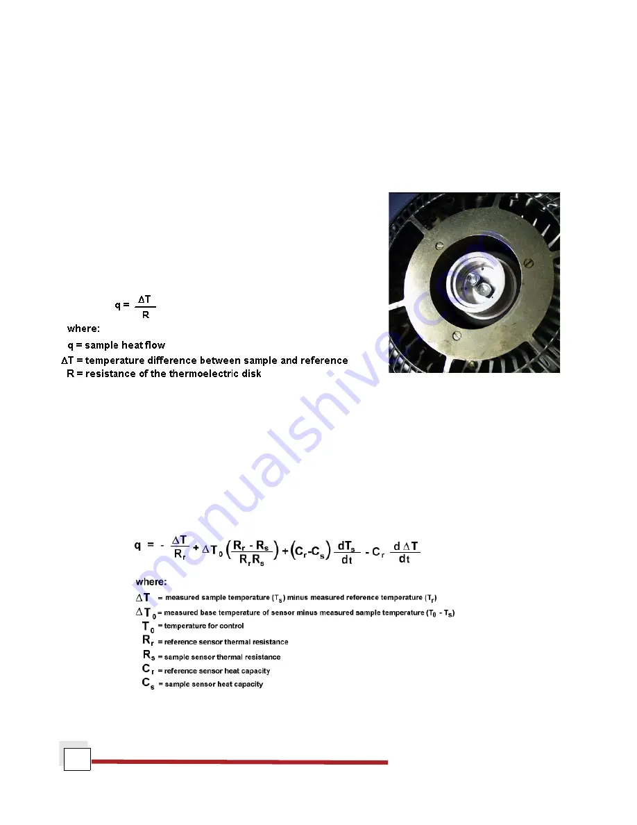
In a "heat flux" DSC, the sample material, encapsulated in a pan, and 
an empty reference pan sit on a thermoelectric disk surrounded by a 
furnace. As the temperature of the furnace is changed (usually by 
heating at a linear rate), heat is transferred to the sample and reference 
through the thermoelectric disk. The differential heat flow to the sample 
and reference is measured by area thermocouples using the thermal 
equivalent of Ohm's Law. 


This simple relationship, however, does not take into account extraneous heat flow within the sensor or between 
the sensor and sample pan. The TA Instruments Q Series DSC's are specifically designed to account for those 
latter heat flows.

The cell sensor consists of a constantan body with separate raised platforms to hold the sample and reference. 
The platforms are connected to the heating block (base) by thin-walled tubes that create thermal resistances 
between the platforms and the base. Area detectors (thermocouples) on the underside of each platform measure 
the temperature of the sample and reference. A third thermocouple measures the temperature at the base. The 
equation below shows the thermal network model which represents this cell arrangement, and the resultant 
heat flow expression that describes this cell arrangement (designated the To [Tzero

TM

] cell) is


The first term in this expression is the equivalent of the conventional single-term DSC heat flow expression. The 
second and third terms account for differences between the sample and reference resistances and capacitances 

Содержание DSC Q Series

Страница 1: ...Revision N Issued January 2007 Q SeriesTM Getting Started Guide DSC Differential Scanning Calorimeter...

Страница 2: ...marks copyrights or other intellectual property covering subject matter in this document Except as expressly provided in written license agreement from TA Instrument the furnishing of this document do...

Страница 3: ...ts Manual Supplement Please click on the links below to access important information supplemental to this Getting Started Guide TA Instruments Trademarks TA Instruments Patents Other Trademarks TA Ins...

Страница 4: ...l 14 Cooling Accessories 15 Finned Air Cooling System FACS 15 Refrigerated Cooling System RCS 16 Quench Cooler 17 Liquid Nitrogen Cooling System LNCS 17 The DSC Q2000 Q200 Touch Screen 18 Primary Func...

Страница 5: ...ssory for FACS 43 Quench Cooler 44 Installation of Additional Items 46 Installing the Manual Lids 46 Installing the Autosampler Tray and Dust Cover 46 Chapter 3 Use Maintenance Diagnostics 47 Using th...

Страница 6: ...lled 58 Burning Off Contamination in a DSC Cell with an RCS or LNCS 59 Removing a DSC Q2000 Q1000 Cell 60 Installing a Cell 60 Replacing Fuses 61 Replacing the DSC Fuses 61 Replacement Parts 62 Fuses...

Страница 7: ...rtant and critical instructions A NOTE highlights important information about equipment or procedures A CAUTION emphasizes a procedure that may damage equipment or cause loss of data if not followed c...

Страница 8: ...eneral Requirements IEC 1010 2 010 1992 Particular requirements for laboratory equipment for the heating of materials Amend ments Electromagnetic Compatibility Standards For Australia and New Zealand...

Страница 9: ...tructed to do so in the manual Maintenance and repair of internal parts must be performed only by TA Instruments or other qualified service personnel Please heed the warning labels and take the necess...

Страница 10: ...ge enough to be removed easily and a rubber apron For extra protection wear high topped sturdy shoes and leave your pant legs outside the tops 2 Transfer the liquid slowly to prevent thermal shock to...

Страница 11: ...injury After running any type of experiment you must allow the DSC cell to return to room temperature before you touch the inner cell surfaces Lifting the Instrument The DSC is a fairly heavy instrum...

Страница 12: ...DSC Q Series Getting Started Guide 12...

Страница 13: ...gineer identify processing and end use performance The DSC instrument works in conjunction with a controller and associated software to make up a thermal analysis system Your controller is a computer...

Страница 14: ...to account extraneous heat flow within the sensor or between the sensor and sample pan The TA Instruments Q Series DSC s are specifically designed to account for those latter heat flows The cell senso...

Страница 15: ...epends on the temperature range that you wish to use for your experiments To install the cooling accessories see Chapter 2 For proper operation the correct cooler type must be selected through the ins...

Страница 16: ...scade vapor compression refrigeration system with an attached cooling head See the figure to the right TheRCS90canbeusedforexperimentsrequiring cooling within an operating range of 90 C to 550 C The m...

Страница 17: ...en using the Quench Cooler NOTE The Quench Cooler requires manual lids and therefore cannot be used with the Autosampler The AutoLid is disabled parked during Quench Cooler operation Liquid Nitrogen C...

Страница 18: ...riment This is the same function as Start on the instrument control software Start automatically loads the sample pan and closes the furnace if necessary before beginning the experiment Stop If an exp...

Страница 19: ...he com mands shown are not avail ableduring an active experi ment Select the desired function either from the drop down list of Control Commands or by pressing the icon Then press Apply to initiate th...

Страница 20: ...park position which is set off to the right and below the home position GO TO STANDBY When using an RCS or LNCS this option will cool to the TEMPERATURE standbytemperatureselectedintheinstrumentcontro...

Страница 21: ...ON Displays instrument information such as the software version options and the IP address STATUS Displays the three main signals indicating the current status of the experiment SIGNALS Displays the r...

Страница 22: ...tom of the touch screen are used to perform the basic functions of the instrument and to access the two main screens See the table below for details Key Name Description Beginstheexperiment Thisisthes...

Страница 23: ...ystem between on and off depending on the state of the RCS when you press the key Toggles between purge Gas 1 and Gas 2 See page 35 for information on gases to be used with the DSC Automatically fills...

Страница 24: ...rently being used and highlights the active segment Displays the three main signals indicating the current status of the experiment Displays instrument information such as the software version options...

Страница 25: ...ng the instrument control software The table below explains the functions of the instrument keys Key Description Start Key This key begins the experiment This is the same function as Start on the inst...

Страница 26: ...nd reference pans to and from the Dif ferential Scanning Calorimeter DSC measurement cell Once the Autosampler loads the pans and the cell covers are in place the controller takes over and runs the pr...

Страница 27: ...ides the following Resolution of overlapping peaks Determination of heats of vaporization and vapor pressure Reaction rates in controlled atmospheres Studies of pressure sensitive reactions The Pressu...

Страница 28: ...eight of Autosampler alone 4 5 kg 10 lbs Weight of transformer 8 6 kg 19 lbs Power 120 Vac 47 63 Hz 500 W 4 5 amps standard 230 Vac 47 63 Hz 500 W 2 25 amps if configured with a voltage configuration...

Страница 29: ...e 0 5 to 100 mg nominal Sample volume 10 mm3 in hermetic pans Sample pans Various open or hermetically sealed standard and Tzero series Purge gases Recommended air argon helium nitrogen or oxygen Typi...

Страница 30: ...DSC Q Series Getting Started Guide 30...

Страница 31: ...nsult the online documentation for additional information Installation involves the following procedures Inspecting the system for shipping damage and missing parts Connecting the DSC to the TA Instru...

Страница 32: ...ruments thermal analysis controller compressed lab air and purge gas supplies with suitable regulators and flowmeters if a mass flow controller MFC is not installed in the instrument Away from dusty e...

Страница 33: ...s nine ports that are located on the back of the instrument The following table provides a description of function of each port Refer to this list when connecting cables and lines Port Function Ethern...

Страница 34: ...d Used for the primary sample purge gas Gas 2 Gas inlet port Used when needed for the secondary sample purge gas if equipped with MFC Cooling Gas Provides air for the Finned Air Cooling System FACS an...

Страница 35: ...struments 5 Check the Ethernet port on the rear of the instrument If communication between the instrument and the switch has been properly established a solid green light and flashing yellow light wil...

Страница 36: ...Locate the second Ethernet port on the back of the computer 2 Plug one end of the Ethernet cable into the computer s Ethernet port 3 Plug the other end into the LAN 4 ChecktheEthernetportontherearoft...

Страница 37: ...d con nect a secondary gas to the Gas 2 port The flow rate is controlled through settings chosen using the instrument control software For older Q100 or Q10 instruments that may not have an MFC it is...

Страница 38: ...he RCS and LNCS see the appropriate Getting Started Guide CAUTION The Cooling Gas line feeds into a pressure regulated valve that is set to 170 kPa gauge 25 psig The source pressure setting should not...

Страница 39: ...hat secure it in place See the figure to the right 3 Disconnect the A10J10 connector from A10P10 located inside the PCU Now connect the A10J10 connector on thevoltageconfigurationunittoA10P10 located...

Страница 40: ...the DSC power entry module CAUTION Before plugging the DSC power cable into the wall outlet make sure the instrument is compatible with the line voltage Check the label on the back of the unit to ver...

Страница 41: ...and wish to use the thermal analysis system for some other task it is recommended that you leave the instrument on To ensure proper shutdown of the instrument it is recommended that you select Control...

Страница 42: ...riments to provide a heat sink for optimum performance To install the FACS follow these instructions 1 Remove the lid s If you do not have an AutoLid on your instrument manually remove the lids If you...

Страница 43: ...er requires a pressurized air source connected to the Cooling Gas fitting Installing the Quench Coolers Installing a quench cooler is slightly different depending on whether you are using the stand al...

Страница 44: ...nit cover out to removeit Thenremovethe screws attaching the cell cover to the unit cover cir cled in the figure to the right Three screws are located on the side Q2000 Q1000 and one is located on the...

Страница 45: ...back into place on the side of the cover 9 Connect the base purge line The system is now ready to receive the quench cooler 10 Select the correct cooler type on the Instrument Prefer ences Cooler Page...

Страница 46: ...y the large upper lid on the top Then you can begin your experiment Installing the Autosampler Tray and Dust Cover When you receive your DSC equipped with an Autosampler the sample tray and dust cover...

Страница 47: ...g or choosing the test procedure and entering sample and instrument information through the TA instrument control software Setting the purge gas flow rate Loading the sample and closing the cell lid S...

Страница 48: ...librate the system For example if you calibrate using nitrogen make your runs with nitrogen Types of Calibration for the DSC DSC Model Tzero Cell Temperature Baseline Pressure Heat Capacity Constant M...

Страница 49: ...nd reference positions Both experiments use the same method beginning with a cell preheat followed by an equilibration at an initial temperature holding isothermal for five minutes heating at constant...

Страница 50: ...optimal calibration and performance Heat Capacity Q2000 Q1000 Calibration Heat capacity can be obtained in a single experiment with the DSC Q2000 Q1000 Heat capacity calibration is required if it is...

Страница 51: ...re recalibration to refine pan placement and pickup capabilities Autosampler calibration involves calibrating both the cell and tray positions These procedures have been automated for ease of useopera...

Страница 52: ...vailable To calibrate both the sample tray and cell areas select Full auto cal To calibrate the sample tray only select Tray auto cal To calibrate the cell areas only select Cell auto cal If you need...

Страница 53: ...from the buttons available To calibrate both the sample tray and cell areas select AUTO CAL To calibrate the sample tray only select TRAY CAL To calibrate the cell areas only select CELL CAL If you n...

Страница 54: ...lanning to run subambient experiments with the LNCS use helium as the purge gas If you are using the LNCS for rapid cooling above ambient i e isothermal crystallization then nitrogen may be used as a...

Страница 55: ...ontherear left platform shown in the figure below Cen tering the pans will give more accurate results 3 Cover the cell If the DSC has an autolid assembly touch the LID CLOSED key on the DSC Control Me...

Страница 56: ...ough the instrument control software touching the STOP key on the instrument touch screen or by pressing the STOP key on the keypad Auto Q20 Q20 Q10 Another function that stops the experiment is REJEC...

Страница 57: ...ion off is not recommended If your baseline appears to show sample contamination try the following recommended cleaning procedure The procedure varies slightly depending upon the type of cell QDSC Sta...

Страница 58: ...ne as a last resort Begin by connecting the air purge See also Connecting Purge Gas Lines and then follow the steps below depending on which cooler is installed NOTE Cleaning of the cell is performed...

Страница 59: ...ut the baselineisstillunacceptable repeattheprocedureabove Ifyouneedtoholdlongeratthehighertemperature to remove the contamination you will need to remove the RCS or LNCS heat exchanger before conduct...

Страница 60: ...tabs shownhere andpull the cover towards you to remove it fully If you do not have an Autosampler you will havetoremoveadditional screws to release the cover Then pull the cover towards you to remove...

Страница 61: ...check or change these fuses 1 Turn the instrument off and remove the power cord 2 Insert a small screwdriver at the edge of the power entry module door and pry it open 3 Insertthe screwdriveron the ed...

Страница 62: ...920223 901 Event cable DSC Cells Lids and Accessories Part Number Description 910824 001 Cell cleaning brush 970020 901 Removable cell Q2000 Q1000 970520 901 Fixed Cell Q200 Q100 Q20 Q10 AQ20 Service...

Страница 63: ...126 901 Autosampler Sample Pan Tray 971012 901 Autosampler Dust Cover 971081 901 Autosampler Cell CalibrationFixture 971092 001 Autosampler Sample Waste Bin Container Tzero Sample Encapsulation Press...

Страница 64: ...m Lids Pkg of 200 900793 901 Aluminum Pans Hermetic Pkg of 200 900794 901 Aluminum Pans Hermetic Pkg of 200 900860 901 Aluminum Hermetic Lids with Pinhole Pkg of 50 900796 901 Coated Aluminum Pans her...

Страница 65: ...ration Reference Materials Part Number Description 915060 901 DSC DTA Temperature Calibration Kit 915061 901 Replacement Certified Indium Reference Material for above kit 900902 901 Indium Calibration...

Страница 66: ...DSC Q Series Getting Started Guide 66...

Страница 67: ...ey 23 Autosampler installing dust cover 46 installing tray 46 Autosampler calibration 51 AUTOSAMPLER key 23 B base purge line 38 base purge port 33 C cable Ethernet 35 cables connecting 33 Calibrate 1...

Страница 68: ...NTROL MENU key 22 controller description 13 cooling accessories 15 42 installing 42 cooling gas line 38 cooling gas port 34 D Differential Scanning Calorimeter DSC additional accessories sample encaps...

Страница 69: ...atibility Standards 8 Ethernet cable connecting computer to LAN 36 Ethernet port 33 Ethernet switch connecting to controller 35 connecting to instrument 35 Event port 33 exothermic reaction 26 experim...

Страница 70: ...hold down thumbscrews 9 Home key 21 hot surface label 9 I Information key 21 installation 31 Autosampler dust cover 46 Autosampler tray 46 DSC Q20 Q10 lids 46 Finned Air Cooling System FACS 42 Quench...

Страница 71: ...down 41 technical specifications 28 unpacking 31 instrument symbols 9 K kinetics of reaction 26 L LAN 36 LID OPEN CLOSED 23 Lid Open Closed 19 lids DSC Q20 Q10 installing 46 liquid nitrogen 10 handlin...

Страница 72: ...1 ports 33 base purge 33 Com 1 33 Com 2 33 cooling gas 34 Ethernet 33 Event 33 Gas 1 33 Gas 2 34 power cable installing 40 power entry module 40 power switch 40 pressure calibration 51 Pressure DSC PD...

Страница 73: ...ry Compliance 8 REJECT key 22 repacking 31 replacement parts 62 Reset Autosampler 19 Reset Saved Parameters 20 robotic device 26 running experiments 54 S Safety 9 burns 11 electrical safety 9 thermal...

Страница 74: ...art 18 START key 22 Start key 25 starting experiment 55 instrument 40 Status key 21 status line 18 22 Stop 18 STOP key 22 Stop key 25 stopping instrument 41 stopping an experiment 56 SWITCH GAS 23 Swi...

Страница 75: ...U ultraviolet light 26 Unload 19 Unload Reference 20 unpacking 31 V visible light 26 voltage configuration unit installing 39 W weight 28...

Страница 76: ...DSC Q Series Getting Started Guide 76...

Отзывы: