


The crossed-out wheeled bin means that within the European Union the product must be taken to separate collection at the product end-of-life.
This applies to your device but also to any accessories marked with this symbol. do not dispose of these products as unsorted municipal waste.
In accordance with the WEEE directive concerning the environment, it is forbidden to abandon used electric or electronic equipment or leave
them at a standard public dump. The equipment must be taken to a collection point for treatment, recovery and recycling of EEE waste, or
returned to its dealer on a 1 for 1 basis (one item of equipment bought for one item of equipment taken back). The user is therefore taking an
environmentally-friendly step and helping to preserve natural resources and protect human health.
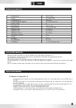
EXTENSION CORDS
Only use extension cords with three conductors ending in two-pin plugs and sockets with two holes and an earth pin that are suited to the plug
of the tool. When using a power tool at a considerable distance from the power source, use an extension cord heavy enough to carry the cur-
rent that the tool will draw. An undersized extension cord will cause a drop in line voltage, resulting in a loss of power and causing the motor to
overheat. Use the chart provided below to determine the minimum wire size required in an extension cord. Only round jacketed extension listed
by laboratories should be used.
Length of extension cord: up to 15 m
Wire size: 3 x 2.5 mm2
Before using an extension cord, inspect it for loose or exposed wires and cut or worn insulation. Repair or replace any damaged or worn cord
immediately.
ELECTRICAL CONNECTIONS
Your machine has a precision built electric motor. It should be connected to a power supply that is 230 V, 50 Hz. If your tool does not operate
when plugged into a socket, double-check the power supply characteristics.
The noise level of the machine is measured according to standards DIN EN ISO 3744: 1995-11 and DIN EN ISO 11203: 1996-07. The values
given are emission values calculated according to applicable standards and not values relating to use in the workplace. Although correlation
between those different emission levels does exist, this cannot be reliably used to determine whether additional precautions are necessary.
Factors with potential influence on the sound emission level in the workplace include the length of the period of work, the size of the room and
any other sources of noise (e.g. number of machines operating, other noisy work being carried out at the same time). Acceptable exposure
levels may vary from one country to another. For all these reasons, we would advise users to wear equipment to protect their ears while using
this machine.
Maximum sound pressure level: 99.6 dB (A)
Maximum sound power level: 112.6 dB (A)
Uncertainties equal: 3 dB
Earthing consists in connecting metal masses, that are liable to come accidentally
in contact with the current due to faulty insulation in an electrical device, to an earth
connection by means of a conductive wire. That earth connection, when used with a
differential circuit breaker, prevents electrical incidents. The current flows directly into
the earth and the power supply is automatically cut off. Do not modify the supplied
plug. If it cannot be put into the socket, have an appropriate socket installed by a qua-
lified electrician. If the earth conductor of a machine is incorrectly connected, this can
lead to a risk of electric shock. The earth conductor is contained in green insulation
with a yellow line. If the power cord needs to be repaired or replaced, do not connect
the earth conductor to a live terminal.
Call in a qualified electrician or maintenance personnel if the earthing instructions
are not fully understood or if in any doubt about the correct earthing of the tool. If the
power supply cable is damaged, it should be replaced by the manufacturer, the manu-
facturer’s after-sales department or similarly qualified person in order to avoid any danger. Do not use a tool if its power cord is damaged. This
tool is designed to be used with a circuit containing a power socket. It is also equipped with an earthing pin.
ENVIRONMENT PROTECTION
CONNECTING THE MACHINE – ELECTRICAL CONNECTIONS
NOISE INFORMATION
EARTHING INSTRUCTIONS
15
Содержание TSR-210
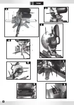
Страница 2: ......
Страница 30: ...5 13 22 6 3 4 5 30 1 6 2 35 6 31 7 15 35 8 9 23 19 16 7 11 5 2 24...
Страница 31: ...VUE CLAT E 31...


