T.O.M TSR-210 Скачать руководство пользователя страница 13

WARNING ! 

Read the instructions in full. Any failure to comply with the instructions 

listed in this document may lead to electric shock, fire hazards or 

serious injury. The term “power tool” mentioned in all of the warnings 

listed below refers both to the power tool when it is connected to the 

mains (by the power cord) and when it operates on its battery (without 

cables). 

PLEASE KEEP THESE INSTRUCTIONS FOR FUTURE 

USE. 

1) Work area 

a) Keep the work area clean and well lit. Cluttered or dark areas invite 

accidents. 

b) Do not operate power tools in explosive atmospheres or in the 

presence of flammable liquids, gases or dust. Power tools generate 

sparks which may ignite the dust or fumes. 

c) Keep onlookers and children away from the work area while ope-

rating a power tool. Distractions can cause you to lose control of the 

tool. 

2) Electrical safety 

a) The power tool plug must correspond to the wall socket. Do not 

modify the plug in any event. Do not use an adapter plug with power 

tools that must be connected to the earth. The original plugs and 

suitable wall sockets reduce the risk of electric shock. 

b) Avoid body contact with earthed surfaces such as piping, radiators, 

refrigerators, etc.  The risk of electric shock is increased if your body 

is connected to the earth. 

c) Do not expose power tools to rain or humidity. Water entering a 

power tool increases the risk of electric shock. 

d) Take care of the electrical cord. Never transport, pull or disconnect 

the power tool by pulling on the cord. Keep the cord away from heat, 

greasy material, sharp edges and moving parts. Damaged or tangled 

cords increase the risk of electric shock. 

e) Only use an extension cord that has been designed for outdoor use 

when operating the power tool outdoors. Using a cord for outdoor use 

reduces the risks of electric shock.

3) Personal safety

a) Stay alert and watch what you are doing. Use common sense 

when operating a power tool. Do not use the power tool when tired 

or under the influence of drugs, alcohol or medication. A moment of 

inattention can lead to serious injury. 

b) Use personal protective equipment. Always wear protective 

goggles. When required, use safety equipment such as a dust mask, 

non-skid safety shoes, a hard hat and hearing protection to reduce 

the risk of injury. 

c) Avoid unintentional starting up. Ensure the switch is in the off-posi-

tion before you connect the tool. 

Carrying power tools with a finger on the switch or connecting them 

with the switch set to on can lead to injuries.

d) Remove any adjustment keys or wrenches before starting up the 

power.

 If a key or wrench remains attached to a moving part, there is a high 

risk of injury. 

e) Do not bend too far over the tool. Keep your balance and a proper 

footing at all times to keep closer control of the power tool in unexpec-

ted situations. 

f) Wear appropriate clothing. Do not wear loose clothing or jewellery.  

Keep your hair, clothing and gloves away from moving parts. Loose 

clothes, jewellery or hair are likely to be caught by moving parts. 

g) If the tool is equipped with a connection for sawdust exhaust or 

dust recovery systems, ensure that they are connected and used cor-

rectly. Using this equipment can reduce the risks connected to dust. 

4) Tool use and care 

a) Do not force the power tool. Use the correct power tool for your ap-

plication. This will provide better results and will be safer if the power 

tool is used at the speed for which it is designed. 

b) Do not use the power tool if it cannot be started up and stopped 

using the switch. A power tool that cannot be controlled by means of 

the switch is hazardous and must be repaired. 

c) Disconnect the power tool from the mains or remove the battery 

before making adjustments, changing accessories or storing it. These 

preventive safety measures reduce the risk of starting the tool acci-

dentally. 

d) Store power tools switched off and out of the reach of children. 

Do not give them to untrained individuals who have never used them 

before and have not read and understood these instructions. Power 

tools can be dangerous in the hands of these individuals. 

e) Take care of you power tools. Check the misalignment or binding 

of moving parts, breakage of any parts and any other condition that 

could hinder the working of the power tool. If the tool is damaged, 

have it repaired immediately. Many accidents are caused by poorly 

maintained power tools. 

f) Keep cutting tools clean and sharpened. Well maintained cutting to-

ols with sharp cutting edges are less like to bind and easier to control. 

g) Use the power tool, accessories, disc pads, etc. in accordance with 

these instructions and according to their characteristics, depending on 

the task to be carried out and the working conditions. Using a power 

tool for reasons other than those for which it was designed can be 

dangerous. 

5) Repairs 

Have your power tool repaired by a qualified technician who only uses 

identical spare parts. This is vital in order to ensure that the power 

tool can be used safely.


GENERAL SAFETY INSTRUCTIONS

13

Содержание TSR-210

Страница 1: ...SCIE A ONGLET RADIALE 210 mm 8 COMPOUND MITER SAW KAPP UND ZUGZ GE 210 mm TSR 210 Manuel d utilisation Operating instructions Bedienungsanleitung...

Страница 2: ......

Страница 3: ...PARTS LIST 33 TSR 210 MOTOR PARTS LIST 36 TSR 210 STAND PARTS LIST 38 CONFORMITY AND WARRANTY 43 DEUTSCH ALLGEMEINE SICHERHEITSREGELN 23 ZUS TZLICHE SICHERHEITSREGELN F R TISCHKREISS GEN 24 SYMBOLE 2...

Страница 4: ...it de transporter les outils lectriques avec un doigt sur l interrupteur ou de les bran cher lorsque l interrupteur est en position marche peut engendrer des accidents d Enlevez les cl s de r glage av...

Страница 5: ...voyez un clairage suffisant pour votre poste de travail ou son environnement imm diat 15 Si la scie est quip e d un laser n utilisez pas d autre type de laser Confiez les r parations exclusivement au...

Страница 6: ...11203 1996 07 Les valeurs cit es sont des valeurs d mission calcul es selon les normes en vigueur et non des valeurs li es l utilisation sur le lieu de tra vail Bien qu il y ait une corr lation entre...

Страница 7: ...0 Poign e de blocage du plateau 11 Rep re pour la graduation 12 Graduation de la table D blocage 13 Manette de blocage de l inclinaison de la t te de scie pour la coupe en biseau 14 Vis de blocage des...

Страница 8: ...ant g n ralement reconnue Le fabricant ne saurait tre tenu pour responsable de toute modification apport e l outil ou de tout dommage pouvant r sulter de telles modifications Enfin l utilisation de ce...

Страница 9: ...ant d actionner l interrupteur MARCHE ARRET s assurer que la lame de scie soit correctement mont e et que les l ments mobiles fonctionnent sans bloquer Avant de raccorder la machine s assurer que les...

Страница 10: ...entre la lame 5 et la table rotative 8 soit de 90 Pour fixer ce r glage serrer nouveau le contre crou Contr ler ensuite la position d angle Si n cessaire desserrer le pointeur avec un tournevis crucif...

Страница 11: ...sens des aiguilles d une montre Apr s un tour au max le dispositif de blocage de scie s encliqu te Desserrer pr sent avec un peu plus de force la vis brid e en la tournant dans le sens des aiguilles...

Страница 12: ...0 MOTOR PARTS LIST 36 TSR 210 STAND PARTS LIST 38 CONFORMITY AND WARRANTY 43 DEUTSCH ALLGEMEINE SICHERHEITSREGELN 23 ZUS TZLICHE SICHERHEITSREGELN F R TISCHKREISS GEN 24 SYMBOLE 25 INSTALLATION 25 SPE...

Страница 13: ...nger on the switch or connecting them with the switch set to on can lead to injuries d Remove any adjustment keys or wrenches before starting up the power If a key or wrench remains attached to a movi...

Страница 14: ...h laser no exchange with different type of laser is permitted Repairs shall only be carried out by the laser manfacturer or an authorized agent 15 Refrain from removing any cut offs or other parts of...

Страница 15: ...lated according to applicable standards and not values relating to use in the workplace Although correlation between those different emission levels does exist this cannot be reliably used to determin...

Страница 16: ...6 Saw blade guard hinged 7 Stop rail 8 turntable 9 Base plate fixed 10 Locking handle 11 Pointer 12 Dial for turntable 13 Locking lever 14 Knurled screw 15 Scale 16 Retaining pin 17 Vise 18 Extensions...

Страница 17: ...is also imperative to observe the accident prevention regulations in force in your area The same applies for the general rules of occupational health and safety The manufacturer shall not be liable f...

Страница 18: ...he rating plate is the same as that for your mains 7 1 Setting up the saw unit Fig 1 2 To adjust the turntable 8 loosen the locking handle 10 by approx 2 turns which frees the turntable 8 Turn the tur...

Страница 19: ...ion adjustment of the stop for crosscut 90 Fig 1 4 Lower the machine head 4 and fasten in place with the safety pin 16 Slacken the tightening screw 13 Place the angular stop a between the blade 5 and...

Страница 20: ...Press the lever and swing up the saw blade guard to the point where the recess in the saw blade guard is above the flange bolt Press the saw shaft lock 24 with one hand while holding the wrench 31 on...

Страница 21: ...LIST 33 TSR 210 PARTS LIST 33 TSR 210 MOTOR PARTS LIST 36 DEUTSCH ALLGEMEINE SICHERHEITSREGELN 23 ZUS TZLICHE SICHERHEITSREGELN F R TISCHKREISS GEN 24 SYMBOLE 25 INSTALLATION 25 SPEZIFIKATIONEN 25 MO...

Страница 22: ...as Tragen von Elektrowerkzeugen mit einem Finger auf dem Schalter oder das Anschlie en bei eingeschaltetem Ger t kann Unf lle verursachen d Vor dem Einschalten des Elektrowerkzeugs Einstellschl ssel a...

Страница 23: ...einen Laser des Herstellers Reparaturen am Laser sollten nur vom Hersteller oder von autorisierten Personen vorgenommen werden 15 Warten Sie bis die Maschine v llig gestoppt hat und der S gekopf in s...

Страница 24: ...n DIN EN ISO 3744 1995 11 DIN EN ISO 11203 1996 07 Bei den angegebenen Werten handelt es sich um gem den geltenden Normen berechnete Emissionspegel und nicht um mit der Verwendung der Maschine am Arbe...

Страница 25: ...8 Drehtisch 9 Feste Grundplatte 10 Schnittwinkelarretierung 11 Zeiger 12 Winkelanzeige des Drehtischs 13 Neigungsarretierung des S gekopfs 14 R ndelschraube 15 Neigungsanzeige des S gekopfs 16 Verrie...

Страница 26: ...allverh tungsvorschriften sowie jegliche sonstigen allgemein g ltigen Gesundheitsschutz und Sicherheits regeln sind unbedingt einzuhalten Der Hersteller bernimmt keinerlei Haftung f r jegliche am Elek...

Страница 27: ...lters sicherstellen dass das S geblatt ordnungsgem montiert ist und bewegliche Teile leichtg n gig sind Vor dem Anschlie en der Maschine sicherstellen dass die Daten auf dem Typenschild mit den Netzda...

Страница 28: ...d Drehtisch 8 90 betr gt Um diese Einstellung zu sichern Gegenmutter wieder festziehen Abschlie end die Position der Winkelanzeige berpr fen Falls erforderlich Zeiger mit Kreuzschlitzschraubendreher l...

Страница 29: ...cken und die Flanschschraube langsam im Uhrzeigersinn drehen Nach max einer Umdrehung rastet die Spindelarretierung ein Jetzt mit etwas mehr Kraftaufwand die Flanschschraube im Uhrzeigersinn l sen Die...

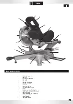
Страница 30: ...5 13 22 6 3 4 5 30 1 6 2 35 6 31 7 15 35 8 9 23 19 16 7 11 5 2 24...

Страница 31: ...VUE CLAT E 31...

Страница 32: ...ship ping charges 3 Reservations The warranty shall not under any circums tances cover repairs carried out by a non au thorised repairer The equipment should not be dismantled under any circumstances...

Отзывы: