13
English
4 - Installation
4.3
Connection to the outdoor unit
When connecting the refrigerant pipes to the outdoor unit consider to
n
Ensure that the actual length of refrigerant piping between the
outdoor unit and the WHE is at least 3 meters
n
Include bends and vertical lines in at least two places
n
A siphon on the gas line at the exit of the WHE unit is recommended
n
Refrigerant piping should be secured with supports at least 1.5
meters from the units and subsequently along the length of the
refrigerant pipework
n
Provide oil traps in order to ensure the correct oil return to the
outdoor unit's compressors
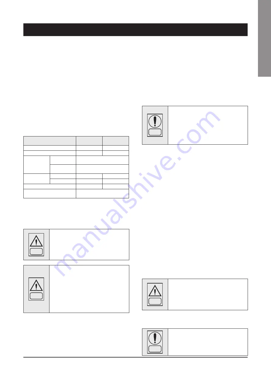
See table below for details on outdoor and indoor connections
WHE indoor unit
PAW-200W5
APAC
PAW-250W5
APAC
Outdoor unit
U-200PZH2E8
U-250PZH2E8
Max total tube length
90 m*
60 m*
Max height
difference
Outdoor located
higher
30 m
Outdoor located
lower
30 m
Connection pipe
diameter
Liquid
9,52 mm
12,7 mm
Gas
28,58 mm
28,58 mm
Additional charge per 1 m
60 g/m
80 g/m
Maximum refrigerant amount
(indoor)
7,8 kg
4.4 External Water Circuit
WARNING
The external water circuit shall guarantee a
constant water flow rate through the circulating
refrigerant/water heat exchanger (evaporator)
under steady operating conditions and in case
of a load variation.
WARNING
An external pump is required to overcome pres-
sure drops of the unit and the system (refer to
unit pressure drop chapter). Connect the digital
input of the pump to the proper clamp of the unit
(see wiring diagram chapter). It is the installer's
responsibility to provide Pump power supply.
Any kind of pump can be connected to the unit
based on user needs. Follow the instruction be-
low for 1 phase or 3 phase pump connection
The circuit shall be composed by the following elements:
n
Provide a circulation pump which can ensure the necessary flow
rate and head
n
Refer to total unit pressure drop for a correct pump selection.
Refer to the next chapter for the electrical connection of the
external pump to the unit
n
The water volume of the primary water circuit, shall never be
lower than 10 lt/kW in terms of refrigerating capacity. In the event
of insufficient water volume, a buffer tank should be installed. This
tank is intended to avoid any repetitive start of the compressor.
n
A membrane expansion tank complete with a safety valve and a
drain which shall be visible.
n
Follow the 3 possible configurations in the figures on the next
page.
NOTE
The expansion tank shall be dimensioned in
such a way that it can absorb 2% expansion
of the total volume of the water in the plant
(exchanger, pipelines, uses and storage tank,
if available). The expansion tank shall never
be insulated when the circulating fluid is not
flowing through it.
A differential pressure switch is mounted as a standard. It will stop
the unit whenever it senses a load loss through the heat exchanger
which may result in a flow rate problem.
A drain pipette is supplied loose as a standard. Install the drain
pipette on the dedicated hole on the low part of the unit as shown in
chapter drainage
In addition it is advisable to:
n
Install on/off valves on the lines at the inlet and outlet of the
manifolds of the exchangers (evaporator).
n
Arrange air vent valves at the high points of the water circuit.
n
Arrange drain points complete with plugs, cocks, etc. in the
proximity of the low points of the water lines.
n
Insulate the water lines to prevent the heat from blowing back into
the unit.
n
Provide a flow rate adjustment valve, so that the hot/cold water
flow rate can be adjusted while watching the water temperature
during testing. Do not touch the adjustment valve after adjusting
n
The hot/cold water flow rate should be within the range shown in
the technical data
WARNING
Before filling the installation, remove any
impurities, such as sand, crushed stones and
welding scales, coating drops and any other
material which might damage the evaporator.
It is advisable to flush with disposable water bypassing the exchanger
to avoid clogging.
NOTE
The water used to fill the circuit shall be treated
in such as way that the pH will have the correct
value. Glycol must not be used.
* Please note the final pipework length may be less than the maximum
shown in order to meet EN 378 installation requirements
Содержание PAW-200W5APAC
Страница 2: ......
Страница 28: ...26 6 Control 6 3 WHE Wiring Diagram ...
Страница 36: ...34 8 Technical Data 8 6 Space Requirements mm min 40 min 1000 min 300 min 100 ...


