33/64 |
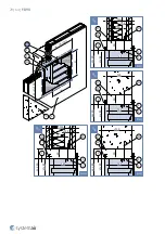
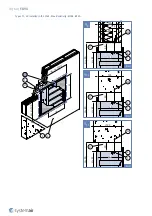
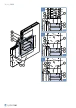
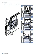
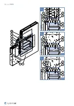
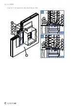
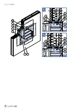
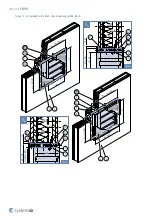
F-B90
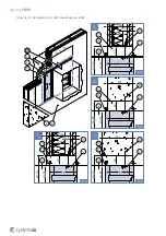
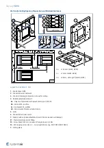
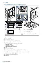
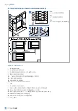
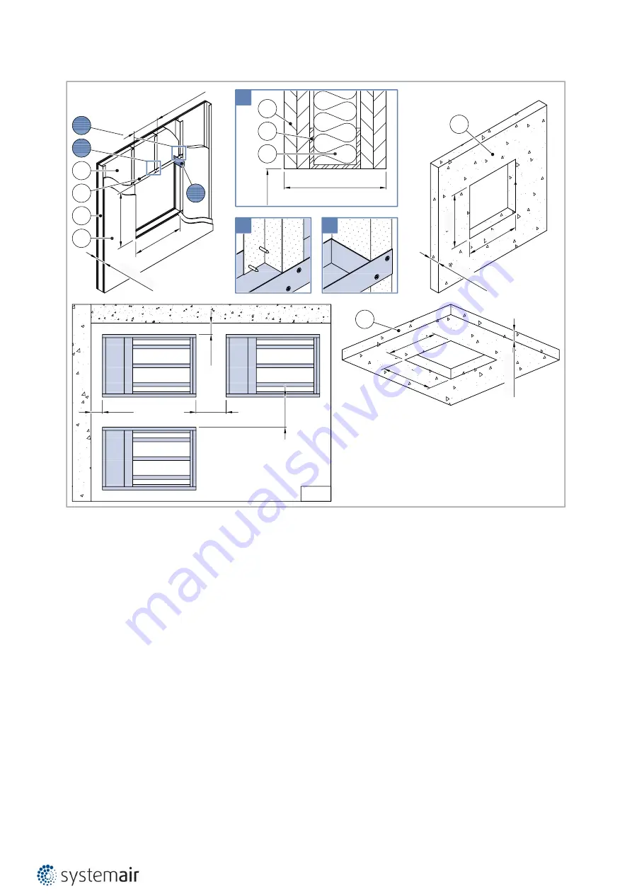
Wall and/or Ceiling Opening Preparation and Minimum Distances
4a:
≥12,5 mm (EI60S, EI90S)
4c:
≥75 mm (EI60S, EI90S)
4d:
≥40 mm; ≥80 kg/m
3
(EI60S, EI90S)
(mm)
H
1
×W
1
≥125 mm
≤62
5 m
m
H
1
W
1
≥125
mm
H
1
W
1
≥75
≥200
≥7
5
≥1
25
m
m
W
1
H
1
≥125
mm
C
B
A
B
C
A
4b
4d
4c
4a
4d
4c
4a
3
3
≥2
00
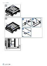
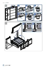
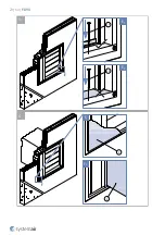
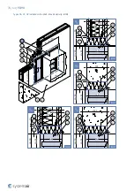
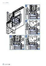
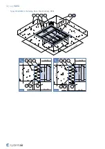
Legend for Installation 1. Wet
1
- Fire damper F-B90
2
- Connected metal ductwork
3
- Concrete/masonry/cellular concrete wall or ceiling
4
- Flexible (plasterboard) wall
4a
- 2 layers of plasterboard fireproof plate type F, EN 520
4b
- Vertical CW – profiles
4c
- Horizontal CW – profiles
4d
- Mineral wool; thickness/cubic density
5
- Grille
6
- Connected extension piece
7
- Façade surface (noncombustible at least 200 mm around duct/damper)
F1
- Plaster/mortar/concrete filling
F2
- Screw M6×20-25 mm, maximum fixing torque is 4,5 Nm
F3
- Self-tapping screw size 4,2 ... 4,8; length 80 mm (e.g. DIN 7981C/DIN 7982C)
Y
- Cutting plane
Содержание 178818
Страница 1: ...F B90 Multiblade Fire Damper Handbook...
Страница 21: ...21 64 F B90 5 1 1 2 B A1 A2 3 A1 B A2...
Страница 22: ...22 64 F B90 C1 C2 C3 C4 C5 i D 4 1 8 1 Fx D1 D2...
Страница 23: ...23 64 F B90 F3 5 2 E F F3 E1 E2 5 F1 F2 6...
Страница 48: ...48 64 F B90 Wire preparation C1 A1 A2 B C2 C2 H B G A1 A2 B 2 1 C2 C1...
Страница 61: ...61 64 F B90 D1 D2 D3 P13 P13 E E H B G 1 2 H...
Страница 64: ...Systemair DESIGN 2021 08 25 Handbook_F_B90_en GB...


