background image

机床产品

/Machine Tool Products

                             – 

                            60W-E Wood Operation Manual

Fenu and System Introduction

                             – 


a.

b.

c.

d.

e.

f.

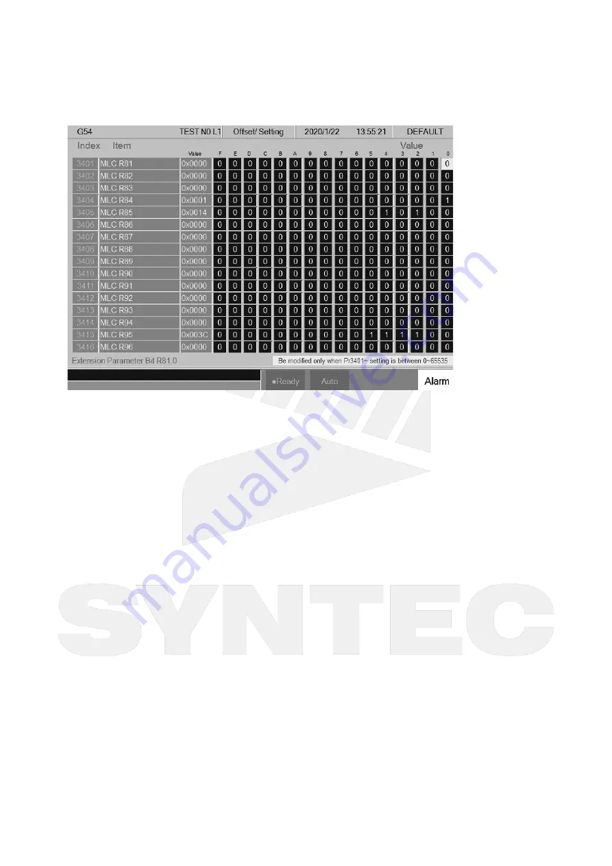
3.8.4  PLC Parameter

Path

5 key, 8 key: F5 Maintain 

 F4 PLC Param.

10+8 key: G5 Maintain 

 F4 PLC Param.

Explanation

Syntec controllers provide R81~R100 total 20 registers for machinery to use, each register can be 
divided into 16 Bits.

With the 20 register sets, machinery can provide users the control flag of specific PLC functions. 

Extended parameters(Pr3401~Pr3420) with value out of the range of 0~65535 are not able to set 
its corresponding register in this screen.

Operation Method

Move the cursor with arrow keys

】【

】【

】【

Use

PageUp

】【

PageDown

 to switch pages.

Users can only input 0 or 1.
Users can add comments to each Bit.
Corresponding file name for the comments is ParamExt_RBit_(L).xml
(L) = COM/CHT/CHS/language

Содержание 60W-E Wood

Страница 1: ...60W E Wood Operation Manual 2022 02 11 2020 11 24...

Страница 2: ...Machine Tool Products 60W E Wood Operation Manual Hardware 60W E Serial bus controller Manual...

Страница 3: ...r 4 Workpiece Coordinate Number 100 BPT 1000 Software Version 10 116 54x 10 118 12x 10 118 x Communication Protocol M3 EtherCAT 60W E Option 4 Axes RTCP Option 29 ROT Option 32 Auto Labeling Machine F...

Страница 4: ...Machine Tool Products 60W E Wood Operation Manual Manual Objective Machine 2 Manual Objective Machine This Operation Manual is suitable for Syntec SCD 60WA and FC 60WA controller...

Страница 5: ...and System Introduction 3 1 Main Screen Screen component description Current Workpiece Coordinate Current Processing file and process line Current Screen Date Time Data Input Hint Controller Status Mo...

Страница 6: ...stem Introduction 3 2 Function key Tree 3 3 Operator Panel MainFenu F1 3 3 1 Operator Panel F1 Process Frame Devide this browser into different part and function of each part is as below Part Item 1 W...

Страница 7: ...efault built in Undone Aligning Working Printing Done Contact Syntec Technician if you have request for new process of the state Information of Workiniglist shows as Sequence NC files Work Station Sta...

Страница 8: ...Machine Tool Products 60W E Wood Operation Manual Fenu and System Introduction Adjust selected item be later Before After...

Страница 9: ...kinglist Add working item to the end of current workinglist For example there are 5 items in Current Workinglist after user chooses another 5 item and add to workinglist there will be 10 items in work...

Страница 10: ...Machine Tool Products 60W E Wood Operation Manual Fenu and System Introduction Reset List Before After...

Страница 11: ...erator Panel NEXT F1 Back to Break Point Press NEXT F1 a pop up show on screen Press Yes Change to Break point process mode Check the focus of the file content is right and execute After finishing thi...

Страница 12: ...process state to be wrong 3 3 6 Operator Panel F5 Clear List Clear workinglist No Item will show on workinglist after use this function 3 3 7 Operator Panel NEXT F4 LogIn Enter username and password t...

Страница 13: ...is corresponding to the panel Execute the process BarCode Scanning Mode Press The Normal Mode button change to Scan Mode Press again back to Normal Mode Scan the barcode and the scanned NCfile will b...

Страница 14: ...of repeat time is 1 every time the process done it will minus 1 time If set it be 10 this file will be repeat executed till the number be 0 3 4 WorkinglistSetting MainFenu F10 F10 F1 There are severa...

Страница 15: ...ntent 3 4 2 Double Work Station Machine Setting This Function is specifically used for machine with 2 stations which allows user place 2 panels on the plate of the machine Sometimes a panel would come...

Страница 16: ...e 0001_F nc 0001_Z nc eliminate _F and _Z get the same result 0001 nc Prefix Example 5_0001 nc 8_0001 nceliminate 5_ and 8_ get the same result0001 nc At least 1 information need to be set in Back sid...

Страница 17: ...paring to example_1 Suffix name Rule Front Side _5 Back Side _8 0001_5 nc 0001_8 nc 0002_5 nc 0002_8 nc 0003_5 nc 0004_5 nc Sort Work Station 0001_8 1 0002_8 2 0001_5 1 0002_5 2 0003_5 1 0004_5 2 3 F_...

Страница 18: ...de panel got the fix string 0001 nc 0002 nc 0002_F nc 0003 nc 0004 nc 0004_F nc Sort Work Station 0001 1 0002_F 2 0003 1 0002 2 0004_F 1 0004 1 3 4 3 Send Files While Generate Workinglist Only When us...

Страница 19: ...close it Step3 Check the load file type in workinglist I use the double sort function But the sort result is not what I want Check the setting of double sort function in workinglist param setting Che...

Страница 20: ...ecute Command F2 Program F1 Execute Function Execute current program and also change the screen to Monitor page Note This function will be disabled during machining 3 5 2 Delete Line Command F2 Progra...

Страница 21: ...F3 Search Replace F2 Replace Function Replace with input text Operation Method Press F2 Replace to replace highlight string with new string If you want to skip the current highlighted string press F1...

Страница 22: ...edit G code easily Insert Cycle Command 5 buttons type F2 Program Next F1 Can Cycle F1 Insert Cycle 8 buttons type F2 Program F4 Can Cycle F1 Insert Cycle Function Insert the required G code Operation...

Страница 23: ...nts and press OK the contents of the current cycle will change 3 5 5 Block Copy Path 5 buttons type F2 Program Next F2 Block Copy 8 Buttons type F2 program F5 Block Copy Function Select cut copy and p...

Страница 24: ...d been Block Cut and Block Copy Operation Method Move the cursor to the desire line and press Start Line and function key End Line enable Press Page Up Page Down to select desired area Press End Line...

Страница 25: ...program Omit the manual input problem Rapid Teach Command 5 Buttons type F2 Program Next F3 Teach F1 Rapid Teach 8 Buttons type F2 Program F6 Teach F1 Rapid Teach Function Add the current absolute co...

Страница 26: ...fine as the ending of the arc Controller will automatically calculate the relation between middle and end point and determine whether to use G02 or G03 The calculation result will be regarded as the i...

Страница 27: ...debug Default display range will be the span of the full program Simulation setting can be modified by F5 simulate Setting Step Command 5 Buttons type F2 Program F5 Simulation F1 Step 8 Buttons type...

Страница 28: ...m in out the simulation window Operation Method Press F3 Zoom there will be a block show up Use can move the window up down left and right Use Page Up Page Down to change the zooming area Press ENTER...

Страница 29: ...rant User can define the quadrant of simulate plane Quadrant can define are as below First Second Third Fourth Simulate Mode Setting profile simulate method Simulation When user go to the Monitor page...

Страница 30: ...Manager Function This function key can manage all of the NC files within the data storage device The device can be setting with Pr3213 Operation Method Use on the key pad to move the cursor to anywher...

Страница 31: ...ar enter the new file name Note Default file name has no file extension If user want to create a new file with file extension such as NC just enter the extension NC as well The length of file name can...

Страница 32: ...change and show the data structure of selected device Use to select file Move the cursor to the import file and press F2 Select or Space to remark file After remarked all of the import file press F1 C...

Страница 33: ...s invalid when machining Choose DNC File Command 5 Buttons type F2 Program F4 File Manager Next F6 Execute 8 Buttons type F2 Program F8 File Manager F6 Execute Function Execute program stored in exter...

Страница 34: ...h arrow keys Use PageUp PageDown to switch between pages Note After setting the workpiece coordinate please set the tool length compensation again Modification Timing External Shift Able to modify Blo...

Страница 35: ...h The G54 X axis value will then become 5 000 Rel Coord Teach Path 5 key 8 key F3 Offset Setting F1 Workpiece Coord F2 Rel Coord Teach 10 8 key G3 Offset Setting F1 Workpiece Coord F2 Rel Coord Teach...

Страница 36: ...e keyed in teaching value Operation Method Move cursor to the modifying workpiece coordinate Input the teaching value Press Inc Input The workpiece coordinate value will then become the value of curso...

Страница 37: ...chine coordinate of Px2 and be recorded on the screen The machine coordinate of workpiece middle point in X axis direction will be calculated using Px1 and Px2 the result will be shown in the Pxm colu...

Страница 38: ...ading the tool to P2 and press Z axis position teach Operation method After setting up following the descriptions place the tool above workpiece upper surface and near the center point distance betwee...

Страница 39: ...n setups only 96 sets for versions before 10 116 36D Parameter Explanation Diameter Geometry G41 G42 Cutter radius Dn compensation please input radius not diameter Diameter Wear Minor modification of...

Страница 40: ...ill be set as current Z axis machine coordinate value valid version from 2 2 0 Press F3 Set Tool Rel Coord the tool length compensation value of where the cursor is located will be set as current Z ax...

Страница 41: ...isplayed and set at the same time The displayed axes must meet the following three conditions at the same time Must be Z axis Must be a linear axis The axis must be visible not hidden Provides 96 sets...

Страница 42: ...t Tool Length F1 Clear Z Coord Function Clear the current Z axis relative coordinate value Tool No Path F3 Offset Setting F2 Tool Set F7 Tool No Function Please refer to chapter 3 4 4 for details Tool...

Страница 43: ...elated machining parameter Parameters Please refer to Mill Parameter Manual for further details 3 7 Monitor MainFenu F4 Path 5 key 8 key F4 Monitor 10 8 key G4 Monitor Function This fenubar group prov...

Страница 44: ...Col No Parameter Set Part Count Screen 2 G code Time Override Screen 3 Spindle Speed Override Loading according to the number of supporting axes support more than 6 axes F5 Tool Wear Set Function Show...

Страница 45: ...how the work record 10 8 key Graph Adjust Function F8 5 key 8 key Clear Accum Cycle Time Function Clear the accumulated machining time to zero 10 8 key File Manager Function F9 5 key 8 key N A Functio...

Страница 46: ...Feed rate Spindle Program Monitor Block This block will display current machining program Yellow bar indicate to the current running block Machining Information Function It is overlap with Process Se...

Страница 47: ...k point initialization about start block go back Tool Data T 4 numbers The first two code are the tool no The last two code are the tool compensate no Display Area of Machining Setting Description Thi...

Страница 48: ...hed to Program if this button is pressed during machining but it s unable to edit the current executing file 3 7 3 Simulation Switch Path 5 key 8 key F4 Monitor F2 Simulation Switch 10 8 key G4 Monito...

Страница 49: ...Command 5 Buttons type F4 monitor Next F2 work record 8 Buttons type F4 monitor F7 work record Description Check current machining record and export to external storage device 3 7 8 Clear Acum Cycle T...

Страница 50: ...driver can be displayed History Alarm Path 5 key 8 key F5 Maintain F1 Alarm F2 History Alarm 10 8 key G5 Maintain F1 Alarm F2 History Alarm Explanation Display the alarm history of the system Attentio...

Страница 51: ...ding order of Cnt Right Alarm detail list Display history of the alarm selected in the left list History records is not limited in 30 Days History records before 30 Days will be displayed in grey text...

Страница 52: ...Maintain F1 Alarm F5 Analyze CNC Explanation Analyze alarms of CNC type The CNC alarms means all alarms excluding the MLC alarms 3 8 2 Set Kernel Server Path 5 key 8 key F5 Maintain F2 Set Kernel Ser...

Страница 53: ...folder at PC end should be the same as the setting at PC end User Name Can be skipped if no account and password is set to protect the folder shared by the Internet disk if do set the corresponding ac...

Страница 54: ...rver immediately 3 8 3 Fast Diagnosis Path 5 key 8 key F5 Maintain F3 Fast Diagnosis 10 8 key G5 Maintain F3 Fast Diagnosis Explanation Display basic system information for diagnosis System Data Path...

Страница 55: ...Wood Operation Manual Fenu and System Introduction Axes Data Path 5 key 8 key F5 Maintain F3 Fast Diagnosis F2 Axes Data 10 8 key G5 Maintain F3 Fast Diagnosis F2 Axes Data Explanation Display basic a...

Страница 56: ...be divided into 16 Bits With the 20 register sets machinery can provide users the control flag of specific PLC functions Extended parameters Pr3401 Pr3420 with value out of the range of 0 65535 are n...

Страница 57: ...s Setting Explanation This page is used for system environment setting Operation Method Move the cursor with Switch pages with PageUp PageDown Input Display Unit Explanation Set the unit of input and...

Страница 58: ...Switch pages with PageUp PageDown Set Default Path 5 key 8 key F5 Maintain F5 Sys Setting F8 Set MMIConfig F4 Set Default 10 8 key G5 Maintain F5 Sys Setting F8 Set MMIConfig F4 Set Default Explanatio...

Страница 59: ...IConfig F6 F7 F8 My Favor 10 8 key G5 Maintain F5 Sys Setting F8 Set MMIConfig F6 F7 F8 My Favor Explanation For 8 key system of ARM controller provides user define function to F6 F7 F8 of first fenub...

Страница 60: ...F5 Maintain F6 Backup Sys Explanation Backup system data as a compressed file and saved into the assigned external device Online Backup Path 5 key F5 Maintain Next F1 Backup Sys F5 Online Backup 8 key...

Страница 61: ...Machine Tool Products 60W E Wood Operation Manual Fenu and System Introduction 3 8 7 System Permissions Path...

Страница 62: ...intain F8 Use Time Setting F8 Require a license to use 10 8 key G5 Maintain F10 Use Time Setting F10 Require a license to use Explanation This fenu button will only be displayed when CNC has an author...

Страница 63: ...5 key F5 Maintain Next Next F4 Authority Management 8 key F5 Maintain Next F4 Authority Management 10 8 key G5 Maintain F9 Authority Management Explanation Set user s access to each function Please re...

Страница 64: ...rd 8 key F5 Maintain Next F5 Reset Password 10 8 key G5 Maintain Next F1 Reset Password Explanation Can be used to reset the password of the machinery 3 8 13 About Path 5 key F5 Maintain Next Next Nex...

Страница 65: ...tem Introduction Normal Axis Information Normal Axis Path 5 key F5 Maintain Next Next Next F5 About F2 Normal Axis Information F1 Normal Axis 8 key F5 Maintain Next F8 About F2 Normal Axis Information...

Страница 66: ...ion Manual Fenu and System Introduction Displays invalid content as N A SPLCA Path 5 key F5 Maintain Next Next Next F5 About F2 Normal Axis Information F2 SPLCA 8 key F5 Maintain Next F8 About F2 Norm...

Страница 67: ...Next Next Next F5 About F2 Normal Axis Information F3 ROT 8 key F5 Maintain Next F8 About F2 Normal Axis Information F3 ROT Explanation Display information of ROT axis Displays invalid content as N A...

Страница 68: ...duction Explanation Display information of ATC axis Displays invalid content as N A Spindle Information Path 5 key F5 Maintain Next Next Next F5 About F3 Spindle Information 8 key F5 Maintain Next F8...

Страница 69: ...About F4 Fitting Information F1 Driver 8 key F5 Maintain Next F8 About F4 Fitting Information F1 Driver Explanation Display information of driver fittings Displays invalid content as N A SRI Path 5 k...

Страница 70: ...nformation 8 key F5 Maintain Next F8 About F5 Machine Builder Information F1 Machine Builder Information 10 8 key G8 System F10 About F5 Machine Builder Information F1 Machine Builder Information Expl...

Страница 71: ...users are permitted to edit machine builder information after logged in the cursor will appear when entering this page If the authority of editing needs to be limited please switch to Authority Manag...

Страница 72: ...Next F5 About F5 Machine Builder Information F2 Product Registration 8 key F5 Maintain Next F8 About F5 Machine Builder Information F2 Product Registration 110 8 key G8 System F10 About F5 Machine Bu...

Страница 73: ...and wait for the controller to create 2D bar code Use APP to scan 2D bar code and register the products If there are multiple 2D barcodes the barcode can be switched by function keys Next and Previou...

Страница 74: ...ivery Backup 8 key F5 Maintain Next F8 About F5 Machine Builder Information F3 Delivery Backup 110 8 key G8 System F10 About F5 Machine Builder Information F3 Delivery Backup Explanation Providing clo...

Страница 75: ...Machine Tool Products 60W E Wood Operation Manual Fenu and System Introduction Online Service Path 5 key F5 Maintain Next Next Next F5 About F6 Online Service...

Страница 76: ...sion controller information CPU board type image file version software version Machine Builder Information What you can see in Machine Builder Information Screen Axis Information Yaskawa YAS drive mod...

Страница 77: ...achine Tool Products 60W E Wood Operation Manual Fenu and System Introduction View changes Add SYNTEC Wechat official account can be skipped if you already have our official account Wait for 2D bar co...

Страница 78: ...a Wechat APP Press OK and the scan box of Wechat will appear scan 2D bar code and the controller information will be uploaded to the customer service request page Fill in the required information Pres...

Страница 79: ...m Introduction 1 2 Wait for 2D bar code Scan 2D bar code Prepare an app with 2D bar code scanning function The apps showed on the controller screen are recommended Scan 2D bar code and the controller...

Страница 80: ...2 also Next and Previous buttons can be used to switch The hotkeys on the operation panel will be disabled when applying the online service action System Permissions Serial No Setting Path 5 key F5 Ma...

Страница 81: ...crypt Button location 5 key F5 8 key F8 10 8 key F10 Option Information Restore Path 5 key F5 Maintain Next Next Next F5 About F7 System Permissions F3 Op Info Restore 8 key F5 Maintain Next F8 About...

Страница 82: ...5 key F5 Maintain Next Next Next F5 About Next F3 SynFactory Binding 8 key F5 Maintain Next F8 About F8 SynFactory Binding 10 8 key G8 System F10 About F8 SynFactory Binding Explanation Display the 2D...

Страница 83: ...m Explanation Display alarm messages on the screen Pending Alarm Path 5 key 8 key F5 Maintain F1 Alarm F1 Pending Alarm 10 8 key G5 Maintain F1 Alarm F1 Pending Alarm Explanation Display current syste...

Страница 84: ...F1 Alarm F3 Save Alarm Explanation Export the alarm contents of current screen to external device Ex the screen is showing Pending Alarm the contents of current alarm can be exported to external devi...

Страница 85: ...ey text color Display IssueTime Content informations Operations Use up down key to move focus Use PageUp Down key to switch pages Change Alarm category list focus to refresh right side detail records...

Страница 86: ...ng a normal cable IP Address and Subnet Mask can then be skipped IP Address Enter the applicable IP address in the domain Subnet Mask Enter the subnet mask of the IP address Should be the same as the...

Страница 87: ...art server while boot Start the server after booting or not Timeout ms Set the acceptable timeout for connection failure Start Server Path F5 Maintain F2 Set Kernel Server F5 Set Kernel Server F1 Star...

Страница 88: ...Manual Fenu and System Introduction System Data Path 5 key 8 key F5 Maintain F3 Fast Diagnosis F1 System Data 10 8 key G5 Maintain F3 Fast Diagnosis F1 System Data Explanation Display basic system and...

Страница 89: ...controllers provide R81 R100 total 20 registers for machinery to use each register can be divided into 16 Bits With the 20 register sets machinery can provide users the control flag of specific PLC f...

Страница 90: ...ys Setting Explanation This page is used for system environment setting Operation Method Move the cursor with Switch pages with PageUp PageDown Input Display Unit Explanation Set the unit of input and...

Страница 91: ...Switch pages with PageUp PageDown Set Default Path 5 key 8 key F5 Maintain F5 Sys Setting F8 Set MMIConfig F4 Set Default 10 8 key G5 Maintain F5 Sys Setting F8 Set MMIConfig F4 Set Default Explanatio...

Страница 92: ...IConfig F6 F7 F8 My Favor 10 8 key G5 Maintain F5 Sys Setting F8 Set MMIConfig F6 F7 F8 My Favor Explanation For 8 key system of ARM controller provides user define function to F6 F7 F8 of first fenub...

Страница 93: ...F5 Maintain F6 Backup Sys Explanation Backup system data as a compressed file and saved into the assigned external device Online Backup Path 5 key F5 Maintain Next F1 Backup Sys F5 Online Backup 8 key...

Страница 94: ...Machine Tool Products 60W E Wood Operation Manual Fenu and System Introduction 3 8 20 About Command...

Страница 95: ...ism parameter range of program stroke and max feedrate speed etc Operation When system is in manual data input mode MDI user should press stop button before setting any parameter unready shown on the...

Страница 96: ...Machine Tool Products 60W E Wood Operation Manual Fenu and System Introduction Key Selections F1 PLC Status Function Display the component states of PLC and state of staircase chart...

Страница 97: ...cts 60W E Wood Operation Manual Fenu and System Introduction F2 Display System Data Function Display current system data refer to application manual for each corresponding meaning of the serial number...

Страница 98: ...ducts 60W E Wood Operation Manual Fenu and System Introduction 3 11 Sys Admin MainFenu F8 F1 Install Software F2 Backup System F3 Restore System F4 Export Import F5 Install Image F6 System Info F7 Upd...

Страница 99: ...ons Emergency stop button is released and no alarm exists system will switch state from Not Ready to Ready Under Busy FeedHold B stop state if user presses Reset system will switch to Ready state 4 1...

Страница 100: ...ld the axis direction key to keep the axis moving uninterrupted JOG speed can be adjusted by G01 Rapid JOG Function Control axis movement toward the selected direction with G00 speed Can control more...

Страница 101: ...peration Press axis direction key X X Y Y Z or turn the direction switch on the manual pulse generator for the direction to move Turn the dial on manual pulse generator clockwise counterclockwise for...

Страница 102: ...tant Otherwise SYNTEC CNC controller will not be allowed to execute AUTO NC files Operation Release emergency stop button CNC status will change NOT READY to READY Select HOME mode Press axis directio...

Страница 103: ...ill add the entered value to machine coordinate and fill in to workpiece coordinate automatically Press Inc Input after entered the increasing value the system will add the entered value to workpiece...

Страница 104: ...rence tool Key in this number to the corresponding tool No If tool break during machining and replace a new tool we need to change to a new tool If the Z cord 0 position already disappear we can use t...

Страница 105: ...re different tool No by tool alignment equipment Because the trigger position of the tool alignment equipment is almost the same User can key in different tool No tip position into workpiece coordinat...

Страница 106: ...tting the XY Ref Coord Teach you will need code 520 enter it and choose yes These vaules will be entered in to Ref coord X and Ref coord Y Move the cursor to Start Coord Z setting the start point for...

Страница 107: ...press Z Mach Coord Teach you can insert the current Z coord value into Start Coord Z Move the cursor to the Min Z Mach H setting the minimum height for the alignment System will pop out warning messa...

Страница 108: ...r the auto alignment Press F10 and then press Z Mach Coord Teach you can insert the current Z coord values into Start Coord Z Move the cursor to the Min Z Mach H setting the minimum height for the ali...

Страница 109: ...ble about Tool No and Tool MG MG5 T 7 means we install tool No 7 at Tool case No 5 This table will renew during change a new tool Time to Modify First initialized when it is made from factory Need to...

Страница 110: ...the first tool and use the second one when the second one is lock or Tool life is end will use the third one and so on Tool information Status L Lock U Unlock If the status of tool is lock that tool...

Страница 111: ...the program will be designated as the machining program Confirmation There are two ways to confirm whether machining program is specified successfully The screen displays the correct machining progra...

Страница 112: ...could check whether MPG simulation is activated successfully or not with two methods No Cycle Start After activate MPG function the G01 percentage in Monitor page is zero nonzero while user does not...

Страница 113: ...der window will pop up Close the MPG shift window Press ESC when the window is displayed When R606 0 turns to 0 from 1 Being switched to other modes except for MDI or Auto mode Able to be operated whe...

Страница 114: ...the required part count is smaller than part count clear to 0 while Cycle Start again Work Record Function Condition None Description Once CNC continues machining when it meets M99 work record functi...

Страница 115: ...an then be skipped IP Address Enter the applicable IP address in the domain Subnet Mask Enter the subnet mask of the IP address Should be the same as the setting at PC end PC Name Name of the connecti...

Страница 116: ...n failure Start Server Path F5 Maintain F2 Set Kernel Server F5 Set Kernel Server F1 Start Server Explanation Start the kernel server immediately 4 4 7 PC Setting XP OS Guest account setting Log in as...

Страница 117: ...hine Tool Products 60W E Wood Operation Manual How to Operate 60 Series Controller 3 Click OK to confirm sharing setting Select Share this folder on the network and Allow network users to change my fi...

Страница 118: ...Machine Tool Products 60W E Wood Operation Manual How to Operate 60 Series Controller 4 Setting PC name and workgroup Start control panel System change to set Computer Name and Workgroup and...

Страница 119: ...ation Manual How to Operate 60 Series Controller 5 remember these setting contents to use later on when setting controller TCP IP setting Start Setting Network connections and right click on Propertie...

Страница 120: ...60 Series Controller Jumper cable without HUB select use the following IP address and enter IP address the forth number is different from controller setting and Subnet mask same with controller settin...

Страница 121: ...Controller 1 2 a VISTA OS Guest account setting Log in as Administrator and select Start Control Panel User Account Guest Sharing Resource Setting Create a sharing folder and change this folder s sett...

Страница 122: ...e 60 Series Controller b c d e 3 Click on share this folder Click on permission Click on add Enter GUEST as the new group name click OK to complete setting Security setting Right click on folder to sh...

Страница 123: ...to Operate 60 Series Controller 4 5 group permissions to maximum Setting PC name and workgroup Start control panel System change to set Computer Name and Workgroup and remember these setting contents...

Страница 124: ...ntrol panel Network and Internet Network and Sharing Center Properties Select internet protocol TCP IP as shown below Jumper cable without HUB select use the following IP address and enter IP address...

Страница 125: ...Machine Tool Products 60W E Wood Operation Manual How to Operate 60 Series Controller Network cable with HUB select Obtain an IP address automatically...

Страница 126: ...Manual How to Operate 60 Series Controller 1 Win 7 OS Sharing resource setting Right click on folder wants to share select share with and specific people Share this folder to everyone and then click S...

Страница 127: ...Machine Tool Products 60W E Wood Operation Manual How to Operate 60 Series Controller Left click on advanced sharing and select share this folder to everyone...

Страница 128: ...s 60W E Wood Operation Manual How to Operate 60 Series Controller Select permission and select full control only read and change Open Network and sharing center select turn off password protected shar...

Страница 129: ...Machine Tool Products 60W E Wood Operation Manual How to Operate 60 Series Controller...

Страница 130: ...Machine Tool Products 60W E Wood Operation Manual How to Operate 60 Series Controller 2 Setting PC name and workgroup Start control panel system and security System change to set Computer Name and...

Страница 131: ...these setting contents to use later on when setting controller TCP IP Setting Double click Internet Protocol Version 4 TCP IPv4 Jumper cable without HUB select use the following IP address and enter I...

Страница 132: ...fer F1 File Import A window will show up on screen press F5 Device Select and move cursor to the desired external device Press Enter to access to the desired external device If the device icon has red...

Страница 133: ...ns that there is no connection between CNC and this external device Press F2 Select to choose file The box will be checked Press F2 again to cancel it Press F3 Select All to select all files Press F4...

Страница 134: ...Machine Tool Products 60W E Wood Operation Manual How to Operate 60 Series Controller While user try to enter a unconnected external device the warning window shows as below...

Страница 135: ...Machine Tool Products 60W E Wood Operation Manual Appendix 5 Appendix 5 1 Contact Window...

Отзывы: