


TermiCom XPe
WWW.SYMCOD.COM
14
Detailed Specifications
TermiCom XPE is provided with several ports allowing the connection of various types of peripherals
according to needs, for example: printers, electronic scales, bar code scanners, sensors…
The default orientation of the connectors is downwards but it is also possible to have them upwards if
specified on order.
Figure 2
TermiCom XPE bottom view
Power button
The power button (figure 2) allows the TermiCom XPe to be powered on or off.
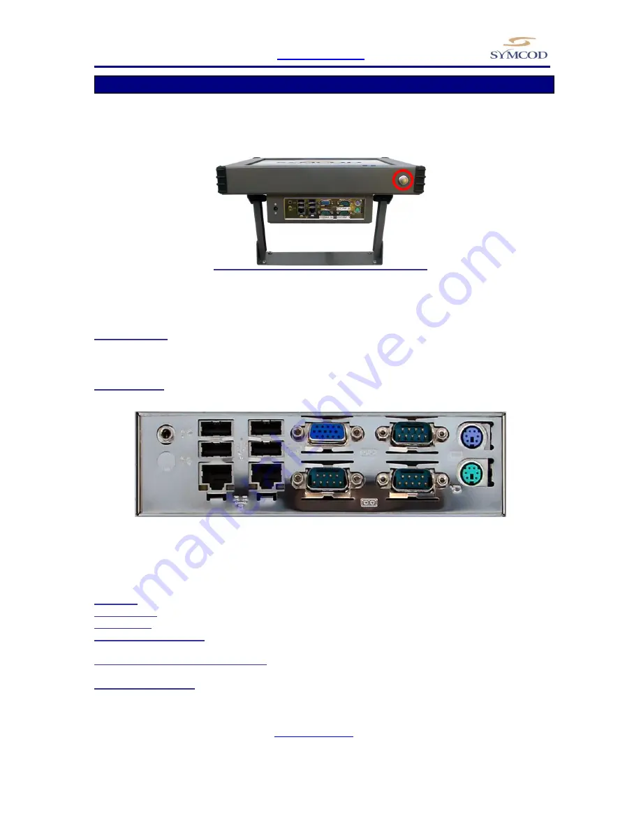
Connectors
Figure 3
TermiCom XPe connectors
Power in:
Allow to connect to a 120 or 240VAC power network (external power supply)
Audio output:
Allow to plug an external audio output
Port SVGA :
Allow to plug a screen
COM 1-2-3 (serial port):
Allow to connect peripherals like printers, electronic scales, automats… with a 9
pins female cable (not included)
USB1, USB2, USB3, USB4 connectors:
Allow to connect USB peripherals, make for “A” type USB
connectors.
2 Ethernet connector :
Allow to communicate through an Ethernet 1Gbit connection with a standard RJ-
45 connector. As any equipment Ethernet that uses cable UTP Cat5, a maximum of 300feet (91.44 meters)
of cable is allowed between the "hub" and/or the "switch" and the TermiCom. For more details concerning
wiring, please download the document "WIRING AND EXAMPLE OF
CONFIGURATION TCPIP" available on
www.symcod.com
.
COM 2
COM 3
SVGA
USB 1, 2, 3 and 4
Ethernet2
Keyboard
Mouse
Audio output
COM 1
Ethernet1


