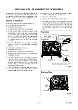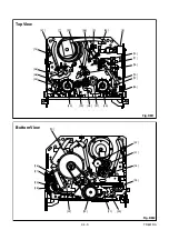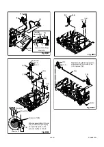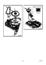
2-4-2
TD601DA
(1): Follow steps in sequence. When reassembling, follow the steps in reverse order.
These numbers are also used as identification (location) No. of parts in the figures.
(2): Indicates the part to start disassembling with in order to disassemble the part in column (1).
(3): Name of the part
(4): Location of the part: T=Top B=Bottom R=Right L=Left
(5): Figure Number
(6): Identification of parts to be removed, unhooked, unlocked, released, unplugged, unclamped, or desoldered.
P=Spring, W=Washer, C=Cut Washer, S=Screw, *=Unhook, Unlock, Release, Unplug, or Desolder
e.g., 2(L-2) = two Locking Tabs (L-2).
(7): Adjustment Information for Installation
(+):Refer to Deck Exploded Views for lubrication.
.
[33]
[2],[25]
M Brake T Assembly
T
DM1,DM16 *(P-6)
[34]
[2],[25]
M Brake S Assembly
T
DM1,DM16 *(P-7)
[35]
[34]
Tension Lever Sub
Assembly
T
DM1,DM16
[36]
[35]
T Lever Holder
T
DM1,DM16 *(L-6)
[37]
[33]
M Gear
T
DM1,DM16 (C-6)
[38]
[2],[15]
Sensor Gear
T
DM1,DM16 (C-7)
[39]
[33]
Reel T
T
DM1,DM16
[40]
[35]
Reel S
T
DM1,DM16
[41]
[31],[35]
Moving Guide S
Preparation
T
DM1,DM17
[42]
[32]
Moving Guide T
Preparation
T
DM1,DM17
[43]
[19]
TG Post Assembly
T
DM1,DM17 *(L-7)
[44]
[19],[28] Rack Assembly
R
DM18
(+)Refer to Alignment
Sec.Pg.2-4-10
[45]
[44]
F Door Opener
R
DM18
*(P-8)
[46]
[46]
Cleaner Lever Assembly
T
DM1,DM6
Type A
*(L-8)
Type B
[47]
[46]
CL Post
T
DM6
*(L-9)
Type A
↓
(1)
↓
(2)
↓
(3)
↓
(4)
↓
(5)
↓
(6)
↓
(7)
STEP
/LOC.
No.
START-
ING
No.
PART
REMOVAL
INSTALLATION
Fig. No.
REMOVE/*UNHOOK/
UNLOCK/RELEASE/
UNPLUG/DESOLDER
ADJUSTMENT
CONDITION
Содержание 6719DC
Страница 58: ...PIN 5 OF CN571 WF12 Q571 Collector WF11 1 11 37 1 11 38 BT5200F01023 A H V CBA Bottom View TV VCR Section...
Страница 98: ...3 1 3 TD500PEX Packing S7 PACKING TAPE S6 X5 TAPE S4 X1 X2 X4 X3 S3 S1 S2...
Страница 123: ...Printed in Japan 2002 06 03 HO 6719DC SSC719C EWC19T2 TD500UA 2UC 3UD...

