background image

6.UMD   

Support “TSL UMD Protocol-V3.1/V4.0” provided by Television System LTD   


Setup Source ID: 

Select “Source ID”, revolve “MENU/ENTER” to select the letters and press “MENU/ENTER" to 

input. Max 8 letters are supported. Select “Exit” to quit and save settings, the source ID will be 

displayed on top or bottom of the screen. 

UMD setup:     

 Connect the external control equipment with S-1273F 

 Set “Display Type” to “UMD” under UMD submenu 

  Set  “Serial  Port”  to  RS485  or  RS232  according  to  the 

port type of external control equipment 

 Make sure the “address”, “Baud Rate”, “Parity” the same   

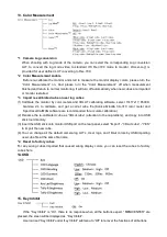
  Adjust  the  external  control  equipment  and  send  UMD 

command,  the  UMD  information  will  be  display  as  the  right 
photo.   

User can set the character and color of the UMD and the color of Tally1 and Tally2. 

RS485 pin sequence and definition:   


RS232 pin sequence and definition:   


Содержание S-1273F

Страница 1: ...Model S 1273F 27 Broadcast Studio LCD Monitor User Manual Ver A SWIT Electronics Co Ltd Please read this User Manual throughout before using ...

Страница 2: ... including scratches cracks or other damage to the LCD screen or other externally exposed parts The LCD dot defects are not over three Any damage caused by using third party power adaptors Any damage or breakdown caused by use maintenance or storage not according to the user manual The product is disassembled by anyone other than an authorized service center Any damage or breakdown not caused by t...

Страница 3: ...e disconnect the power cable under the following situations A If you do not operate this monitor for a period of time B If the power cable or power adaptor is damaged C If the monitor housing is broken The monitor 1 Please don t touch the screen with your fingers which would probably deface the screen 2 Please don t press the screen the LCD is extremely exquisite and flimsy 3 Please don t lay this...

Страница 4: ...V178 It supports 2 x 3GSDI Level A B 1 x HDMI 1 x CVBS 1 x Y Pb Pr 1 x VGA and 1 x analog audio input It also supports 2 x 3GSDI 1 x HDMI 1 x CVBS and 1 x analog audio loop through output Features Support multiple Aspect Ratio and scan modes Support multiple Marker selection Marker Safety Area Powerful audio and video analysis functions Support multiple functions user defined Source ID function ke...

Страница 5: ...S 7004S Gold mount battery plate S 7004A 1 Battery plate Installation 1 Take off the rub cover on the rear panel see Fig 1 2 Insert the DC cable of S 7004S A into the hole and plug onto the power socket inside the hole see Fig 2 3 Fix the battery plate onto the rear panel by the supplied screws see Fig 3 S 7004S S 7004A Fig 1 Fig 2 Fig 3 ...

Страница 6: ...f the waveform DISPLAY Press DISPLAY to turn on or turn off relevant status information audio and video waveform Press DISPLAY to release one key quit the menu when Menu is opened 4 Rotary Knob MENU ENTER When the menu is inactivated press MENU ENTE to turn on the main menu Revolve MENU ENTER to adjust settings or parameters and press to apply When the menu is inactivated revolve MENU ENTER to adj...

Страница 7: ...ant parameters like position audio channels and blending etc can be changed under Audio Bar submenu User can set function Keys F1 F4 or GPI pins as Audio Bar to turn on or off this function Histogram User can set function Keys F1 F4 or GPI pins as Histogram to turn on or off this function Vector The relevant parameters like Vector position Vector color and Vector blending etc can be changed under ...

Страница 8: ...I and HDMI represents saturation as distance from the center of the circle and hue as the angle in standard position around it Histogram R G B The histogram is a bar graph that shows the distribution of luminance values in the picture There re R G B histograms that individually displayed simultaneously available under both SDI and HDMI Internal Color Bar Under SDI and HDMI input it has 100 interna...

Страница 9: ... on the bottom of screen for reference The color from the dark to the bright will be displayed as blue cyan green yellow orange and red in a consecutive way User can set function Keys F1 F4 or GPI pins as False color to turn on or off this function AFD SDI It is the abbreviation of active format description AFD is to display the SDI embedded AFD information graphically on the screen H V Delay SDI ...

Страница 10: ...p stand installation 1U plastic bump Protect the BNC sockets on the rear panel Socket1 RS 485 IN OUT TSL UMD control port GPI GPI control port Y Pb Pr Y Pb Pr input CVBS IN CVBS input BNC connector CVBS OUT VBS output BNC connector Socket 2 RS 232C TSL UMD control port VGA IN VGA input HDMI IN OUT HDMI input output HDMI A connector SDI IN1 SDI input BNC connector SDI OUT1 SDI loop through output f...

Страница 11: ...ded to adjust press MENU ENTER the selected item and its parameters will be highlighted in yellow 4 Revolve MENU ENTER to change the selected item s parameter press MENU ENTER to apply and save the settings 5 Revolve MENU ENTER to select Exit press MENU ENTER to quit submenu Select Exit Status under the Main Menu and press to quit Main Menu Notice The items in gray can not be set up If there is no...

Страница 12: ... as down below 1 Display the current video signal and format 2 Display the current function keys setup 2 Picture To adjust picture parameters 3 Color Temp To select different color temperature or setup user defined color parameters Only Color Temp is set to User the Red Blue Green Gain or Red Blue Green Bias can be adjusted ...

Страница 13: ...ed through external GPI control unit 2 The GPI pins can be setted to the down below functions Red Tally Green Tally Yellow Tally Aspect Ratio Scan Mode Zoom Mode Mute Freeze Frame Flip Mode Color Temp Time code Zebra Vector Audio Bar Histogram False Color AFD H V Delay R G B Mono Marker Color Bar UMD Audio Alarm Focus Assist When connecting the GPI pin with ground the setted function will be turne...

Страница 14: ... UMD setup Connect the external control equipment with S 1273F Set Display Type to UMD under UMD submenu Set Serial Port to RS485 or RS232 according to the port type of external control equipment Make sure the address Baud Rate Parity the same Adjust the external control equipment and send UMD command the UMD information will be display as the right photo User can set the character and color of th...

Страница 15: ... 95 of actual display screen When Fit Marker is On the size of safety area is benchmarked against the area inside the scales marker accounting for 80 95 of the area inside the scales marker Example Aspect ratio 4 3 Aspect ratio 4 3 Safety Area 85 Safety Area 85 Center Marker On Center Marker Off Fit Marker Off Fit Marker On ...

Страница 16: ...low the audio bar will display MUTE 4 Audio channels can be selected to output according to the requirements When the current Select Channel is set to Channel1 2 the left channel and right channel output can be selected from Channel1 or channel2 When the current Select Channel is set to Channel1 8 the left channel and right channel output can be selected from Channel1 to channel8 When the current ...

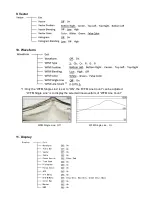
Страница 17: ...10 Waveform 1 Only the WFM Single Line is set to ON the WFM Line Count can be adjusted WFM Single Line is to display the selected line waveform of WFM Line Count WFM Single Line Off WFM Single Line On 11 Display ...

Страница 18: ...or will turn to green energy saving mode that is Green mode For example Set the Green Mode to Standby and Idle Duration to 2Hours if no recognizable signal is detected for 2 hours the montor will turn to standby mode Under standby Gray Backlight Blacklight mode press any button on the front panel the monitor will be back to normal operation status 4 5 Update Driver Kernel Download latest firmware ...

Страница 19: ... 17x17x17 6500K Gamma 2 4 to calibrate and get a corret cube file Konica Minolta CA 310 color meter and Spectracal CalMAN software are recommanded for accurate calibration 2 Rename the re calibrated cube as 3DLut cube attention to the cap lettters and copy into USB stick root directory 3 Insert the USB stick onto monitor USB port on the rear panel select Import 3DLut cube YES to import the new cub...

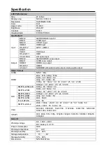
Страница 20: ...HDMI 480i 576i 480p 576p 1080i 60 59 94 50 720p 60 59 94 50 1080p 60 59 94 50 30 29 97 25 24 23 98 1080psf 30 29 97 25 24 23 98 SDI SMPTE 425M A B 1080p 60 59 94 50 SMPTE 274M 1080i 60 59 94 50 1080p 30 29 97 25 24 23 98 SMPTE RP211 1080psf 30 29 97 25 24 23 98 SMPTE 296M 720p 60 59 94 50 SMPTE 125M 480i 59 94 ITU R BT 656 576i 50 SMPTE 2048 2 2048 1080p 23 98 24 25 29 97 30 50 59 94 60 2048 1080i...

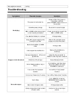
Страница 21: ...olor abnormal Bad contact of BNC or HDMI cable Change cable Video signal has Interference Remove the interference source s Improper adjustment of the color parameters Adjust the Recall profile to Default under System submenu Distortion of the image Reset the Aspect ratio Set to Red Green Blue only or Mono Turn the Blue only Red Only Green Only Mono off under R G B Mono submenu Turn on the Focus As...

Страница 22: ......
Отзывы: