SVS-VISTEK
Feature-Set
72
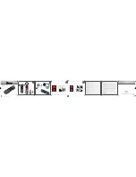
Figure 47: Illustration of schematic wiring with 4IO model using the break out box (matrix)
The pulseloop module
A fully programmable timer/counter function with four individual pulse
generators (pulseloop0 - 3) that can be combined with all SVCam I/O
functions, as well as physical inputs and outputs. All timing settings are
programmable in 15ns intervals.
P
R O G R A M M A B L E P A R A M E T E R S
:
>
Trigger source (hardware or software)
>
Edge or level trigger (HW trigger)
>
Pulse output starting on low or high level
>
Pre and post duration time
>
Number of loops
E
X A M P L E A P P L I C A T I O N S
Initiated by an external trigger, the camera drives an LED illumination
directly from the open drain output and initiates the camera exposure
after a pre-defined delay.
Figure 48: pulseloop for strobe and exposure
Содержание eco4050
Страница 1: ...2 26 2018 Manual EVO series evo1050 evo2050 evo2150 eco4050 evo4070 evo8051 ...
Страница 14: ...SVS VISTEK Getting Started 14 Installation will proceed 8 Installation completed ...
Страница 16: ...SVS VISTEK Getting Started 16 Conform to GenICam all control features will be listed in a flat tree diagram ...
Страница 21: ...SVS VISTEK Getting Started 21 4 5 Driver Circuit Schematics Figure 5 basic Illustration of driver circuit ...
Страница 23: ...SVS VISTEK Connectors 23 ...
Страница 29: ...SVS VISTEK Dimensions 29 ...
Страница 32: ...SVS VISTEK Dimensions 32 ...
Страница 33: ...SVS VISTEK Dimensions 33 ...
Страница 57: ...SVS VISTEK Feature Set 57 ...
Страница 66: ...SVS VISTEK Feature Set 66 Figure 43 I O Lines with open end indicate physical in and outputs ...
Страница 76: ...SVS VISTEK Feature Set 76 Strobe Control Example Setup Figure 50 Illustration of an application using the 4IO ...
Страница 129: ...SVS VISTEK Troubleshooting 129 Space for further descriptions screenshots and log files ...
Страница 131: ...SVS VISTEK IP protection classes 131 ...