


SVS-VISTEK–Getting Started Contents of Camera Set
10
4
Getting Started
4.1
Contents of Camera Set
>
Camera
>
Power supply (if ordered/option)
>
DVD
>
3D CAD files
>
Manuals
>
Software: GigE-Kit (Win 32/64 & Linux)
4.2
Power supply
Connect the power supply.
CAUTION! – This camera does not support hotplugging
1.
First, connect the data cable.
2.
Then connect power supply.
When using your own power supply (e.g. 10 -25 V DC) see also Hirose
12-pin for a detailed pin layout of the power connector. For power input
specifications refer to specifications.
4.3
Camera status
On power up, the camera will indicate its current operation status with a
flashing LED on its back. The LED will change color and rhythm.
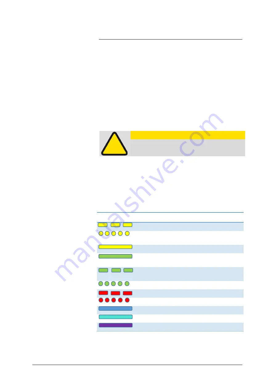
The meaning of the blinking codes translates as follows:
Figure 1: Camera status LED codes
Flashing
Description
Yellow slow (1Hz)
No Connection
Yellow quickly ( 8 Hz )
Assignment of Network
address
Yellow permanent
Network address assigned
Green permanent
Connected with
application
Green slow (1Hz)
Streaming channel
available
Green quickly ( 8 Hz)
Acquisition enabled
Red slow ( 1 Hz )
Problem with initialization
Red quickly ( 8 Hz)
Camera overheating
Blue permanent
Waiting for trigger
Cyan permanent
Exposure active
Violet permanent
Readout/FVAL
Содержание eco4050
Страница 1: ...2 26 2018 Manual EVO series evo1050 evo2050 evo2150 eco4050 evo4070 evo8051 ...
Страница 14: ...SVS VISTEK Getting Started 14 Installation will proceed 8 Installation completed ...
Страница 16: ...SVS VISTEK Getting Started 16 Conform to GenICam all control features will be listed in a flat tree diagram ...
Страница 21: ...SVS VISTEK Getting Started 21 4 5 Driver Circuit Schematics Figure 5 basic Illustration of driver circuit ...
Страница 23: ...SVS VISTEK Connectors 23 ...
Страница 29: ...SVS VISTEK Dimensions 29 ...
Страница 32: ...SVS VISTEK Dimensions 32 ...
Страница 33: ...SVS VISTEK Dimensions 33 ...
Страница 57: ...SVS VISTEK Feature Set 57 ...
Страница 66: ...SVS VISTEK Feature Set 66 Figure 43 I O Lines with open end indicate physical in and outputs ...
Страница 76: ...SVS VISTEK Feature Set 76 Strobe Control Example Setup Figure 50 Illustration of an application using the 4IO ...
Страница 129: ...SVS VISTEK Troubleshooting 129 Space for further descriptions screenshots and log files ...
Страница 131: ...SVS VISTEK IP protection classes 131 ...


