Suzuki K9K Скачать руководство пользователя страница 14

ENGINE MECHANICAL (K9K ENGINE) 6A2-15

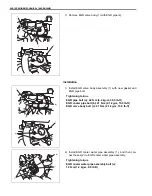
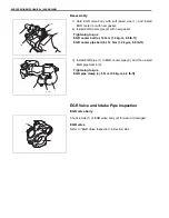
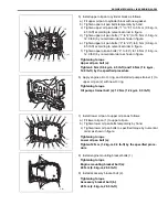
4) Install oil filter unit bracket (1) as shown in figure.

Tightening torque
Oil filter unit bracket bolt (a): 45 N·m (4.5 kg-m, 32.5 lb-ft)

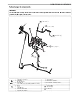
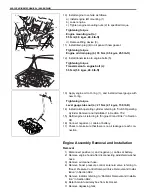
5) Install generator and compressor bracket (1) referring to 

“Generator Drive Belt Tensioner Components” in section 
6H2.

6) Install compressor referring to “Compressor” in Section 1B.
7) Install generator referring to “Generator Dismounting and 

Remounting” in Section 6H2.

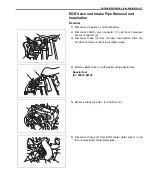
8) Connect oil pressure switch connector (1).
9) Install degassing tank to its bracket.

10) Refill engine coolant referring to “Coolant Replacement” in 

section 6B2.

11) Check engine oil level referring to “Engine Oil and Filter” in 

Section 0B.

12) Check to make sure that there is no oil leakage and coolant 

leakage at each connection.
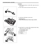
NOTE:

Be sure to align lug (2) of oil filter unit bracket (1) with 
hole (3) of heat exchanger (4).

1

(a)

2

3

4

1

1

1

Содержание K9K

Страница 1: ...ed only by an authorized SUZUKI dealer Refer to Air Bag System Components and Wiring Location View under General Description in air bag system section in order to confirm whether you are performing se...

Страница 2: ...ld as SUZUKI authorized replacement parts and accessories Some genu ine SUZUKI parts and accessories are sold as re use parts and accessories These parts and accessories are non genuine Suzuki parts a...

Страница 3: ...Suspension 3E Automatic Transmission 7B 4B 7D Wheels and Tires 3F Clutch M13 Engine Model 7C 7E DRIVE SHAFT AND PROPELLER SHAFT Clutch K9K Engine Model 7C2 5 7F Propeller Shafts 4B Transfer 7D 5E BRAK...

Страница 4: ...e and remove oil pressure gauge and attachment 8 Reinstall oil pressure switch 1 and tighten switch to speci fied torque Tightening torque Oil pressure switch a 35 N m 3 5 kg m 25 5 lb ft 9 Connect oi...

Страница 5: ...d 7 e In the same manner as b c check valve lashes at valves 2 and 3 If valve lash clearance is out of specification record valve lash clearance and adjust it to specification by replacing tappet Refe...

Страница 6: ...referring to Measurement of Valve Lash Clearance under Valve Lash Clearance in this section 7 Install cylinder head cover referring to Cylinder Head Cover Removal and Installation in this section Thi...

Страница 7: ...t Replace if excessively dirty filter Cleaning When cleaning filter blow off dust by compressed air from air out let side of filter i e the side facing up when installed in air cleaner case Air Cleane...

Страница 8: ...cooler Components 1 a 1 Intercooler 8 Intercooler bracket bolt 2 Intercooler bracket 9 Intercooler hose clamp No 1 3 Intercooler hose clamp 10 Intercooler hose clamp No 2 4 Intercooler outlet hose No...

Страница 9: ...4 Installation Reverse removal procedure for installation noting the following Install intercooler hose clamp 1 in specified direction as shown in figure Tighten intercooler bracket bolts and interco...

Страница 10: ...move injector cover 1 generator upper bracket 2 tim ing belt upper cover 3 and injector return hose cover 4 Disconnect breather hose from cylinder head cover 1 Cylinder head cover bolt Tighten 12 N m...

Страница 11: ...d cover bolts temporarily by hand c Tighten cylinder head cover bolts specified torque by numerical order as shown in figure Tightening torque Cylinder head cover bolt a Tighten 12 N m 1 2 kg m 9 0 lb...

Страница 12: ...switch a 35 N m 3 5 kg m 25 5 lb ft 3 Connect oil pressure switch connector 2 4 Install degassing tank to its bracket 5 Start engine and check for oil leakage Heat Exchanger Removal and Installation...

Страница 13: ...ngine left mounting bracket 2 and then remove heat exchanger 3 Installation 1 Install heat exchanger 1 with new gasket Tightening torque Heat exchanger bolt a 45 N m 4 5 kg m 32 5 lb ft 2 Install engi...

Страница 14: ...r in Section 1B 7 Install generator referring to Generator Dismounting and Remounting in Section 6H2 8 Connect oil pressure switch connector 1 9 Install degassing tank to its bracket 10 Refill engine...

Страница 15: ...2 EGR cooler bolt 20 O ring 5 EGR valve body 13 Intake pipe No 2 bolt Tightening torque 6 EGR cooler water pipe 14 EGR valve bolt Do not reuse 7 EGR valve 15 EGR cooler water pipe bolt 8 EGR pipe bolt...

Страница 16: ...and boost pressure sensor connector 2 3 Disconnect hose 3 from oil vapor recirculation valve 4 and then remove oil vapor recirculation valve 4 Remove EGR valve 1 with gasket using special tool Specia...

Страница 17: ...htening torque EGR pipe bolt a 42 N m 4 2 kg m 30 5 lb ft EGR cooler pipe bolt b 21 N m 2 1 kg m 15 5 lb ft EGR valve body bolt c 21 N m 2 1 kg m 15 5 lb ft 2 Install EGR cooler water pipe assembly 1...

Страница 18: ...ightening torque EGR valve bolt a 12 N m 1 2 kg m 9 0 lb ft 6 Install oil vapor recirculation valve 5 and then connect hose 2 to oil vapor recirculation valve 7 Connect EGR valve connector 3 and boost...

Страница 19: ...r bolt a 12 N m 1 2 kg m 9 0 lb ft EGR cooler pipe bolt b 12 N m 1 2 kg m 9 0 lb ft 3 Install EGR pipe 1 to EGR cooler pipe 2 and then install EGR pipe clamp 3 Tightening torque EGR pipe clamp a 5 N m...

Страница 20: ...rbocharger nut 2 Turbocharger Do not disassemble 9 Turbocharger oil return bolt 3 Lubrication pipe Apply thread lock LOCTITE FRENETANCH to thread part 10 Boost pressure control solenoid valve 4 Gasket...

Страница 21: ...e turbocharger oil return pipe 2 from cylinder block Installation 1 Clean mating surfaces of turbocharger exhaust pipe No 1 and exhaust manifold 2 Apply engine oil to new O ring and install turbocharg...

Страница 22: ...cate turbo charger 12 Check to make sure that there is no oil leakage and exhaust gas leakage at each connection Turbocharger Inspection Rotate turbine shaft 1 by hand and verify that it turns smoothl...

Страница 23: ...nder head with new gasket b Tighten exhaust manifold nuts temporarily by hand c Tighten exhaust manifold nuts specified torque by numeri cal order as shown in figure Tightening torque Exhaust manifold...

Страница 24: ...661 referring to Installation under Oil Pan and Oil Pump Strainer Removal and Installa tion 10 Lower oil pan 16 Level gauge tube 5 Upper oil pan bolt Tighten 6 N m 0 6 kg m 4 5 lb ft and 16 N m 1 6 kg...

Страница 25: ...nsmission Dismounting and Remounting in Section 7A2 6 To facilitate and ensure removal of oil pan increase clear ance between engine and vehicle body according to the fol lowing procedures a Install l...

Страница 26: ...oil pan 12 Remove oil pump strainer 1 from upper oil pan 2 13 Loosen upper oil pan bolts in numerical order 1 to 20 as shown in figure and remove them 14 Remove upper oil pan from cylinder block 15 R...

Страница 27: ...pump strainer screen 1 3 Install oil pan baffle plate to upper oil pan Tightening torque Oil pan baffle plate bolt a 8 N m 0 8 kg m 6 0 lb ft 4 Apply sealant A to cylinder block and gasket holder sea...

Страница 28: ...1 6 kg m 12 0 lb ft by the specified procedure 6 Apply engine oil to O ring and install oil pump strainer 1 to upper oil pan 2 with new O ring Tightening torque Oil pump strainer bolt a 12 N m 1 2 kg...

Страница 29: ...m 2 1 kg m 15 5 lb ft 14 Install clutch operating cylinder referring to Clutch Operating Cylinder Removal and Installation in Section 7C2 15 Refill engine oil referring to Engine Oil and Filter in Sec...

Страница 30: ...wire harnesses from clamps ECM connectors 1 MAF and IAT sensor connector 2 Main fuse box connectors 3 and 4 Engine harness to main harness connector 5 Magnet clutch connector 6 of A C compressor Suppl...

Страница 31: ...K9K ENGINE 16 Install lifting device 1 17 Remove engine mounting nuts 2 18 Before lifting engine check to ensure all hoses electric wires and cables are disconnected from engine 19 Remove engine asse...

Страница 32: ...ts which have not been rein stalled Refill engine oil referring to Engine Oil and Filter in Section 0B Refill cooling system referring to Coolant Replacement in Section 6B2 After connecting discharge...

Страница 33: ...tensioner bolt 14 CMP sensor 3 Timing belt lower cover 9 Timing belt tensioner 15 CMP sensor bolt 4 Crankshaft pulley bolt Tighten 120 N m 12 0 kg m 87 lb ft and 95 by the specified pro cedure 10 Tim...

Страница 34: ...ine Assembly Removal and Installation in this section 2 Remove injector cover 1 and generator upper bracket 2 3 Remove timing belt upper cover 1 after unhooking its tabs 2 4 Remove CMP sensor 3 5 Remo...

Страница 35: ...shaft pulley hub 2 matches with hole 3 of cylinder head 9 Insert special tool A into TDC pin hole as shown in figure Special tool A 09919 58110 10 Turn crankshaft pulley clockwise until crankshaft tou...

Страница 36: ...ing belt 1 15 Remove timing belt tensioner 5 timing belt pulley and tim ing belt inner cover 4 if necessary Installation 1 Clean mating surface of oil pump pulley crankshaft timing belt pulley and cra...

Страница 37: ...iming belt tensioner 2 to specified position as shown in figure by turning timing belt tensioner counterclockwise And then tighten timing belt tensioner bolt 4 to specified torque Tightening torque Ti...

Страница 38: ...y bolt a 14 N m 1 4 kg m 10 5 lb ft 9 Remove special tools A and B 10 Install crankshaft pulley bolt with washer temporarily 11 Turn crankshaft two revolutions clockwise and stop it just before aligni...

Страница 39: ...tensioner bolt 1 while holding timing belt tensioner by hexagon wrench and then gradually bring movable index 3 to center of timing window 2 turing tim ing belt tensioner b Tighten timing belt tensio...

Страница 40: ...f timing belt pulley and cylinder head smoothly If not remove timing belt and return to step 4 Special tool B 09919 58120 22 Install crankshaft pulley as follows a Lock flywheel using special tool C T...

Страница 41: ...lt lower cover 1 hooking its tabs 2 and install its plastic bolt 3 26 Install timing belt upper cover 1 hooking its tabs 2 27 Install CMP sensor 3 Tightening torque CMP sensor bolt 8 N m 0 8 kg m 6 0...

Страница 42: ...NICAL K9K ENGINE 6A2 43 Timing Belt and Belt Tensioner Inspection Inspect timing belt for wear or crack Replace it as necessary Inspect timing belt tensioner and roller for smooth rotation Replace it...

Страница 43: ...ction CAUTION Never disassemble oil pump Disassembly will spoil its original function If faulty condition is found replace it with new one 1 Oil pump drive sprocket 5 Gasket holder plate oil seal Appl...

Страница 44: ...Installation in this section 5 Remove gasket holder plate 1 6 Remove gasket holder plate oil seal 2 7 Remove oil pump chain 1 and oil pump drive sprocket 2 Installation 1 Install oil pump 1 oil pump...

Страница 45: ...proce dure 3 Install upper oil pan and lower oil pan referring to Oil Pan and Oil Pump strainer Removal and Installation in this sec tion 4 Install new gasket holder plate oil seal 1 to gasket holder...

Страница 46: ...erring to Timing Belt and Belt Tensioner Removal and Installation in this section 6 Install engine assembly to vehicle referring to Engine Assembly Removal and Installation in this section Oil Pump an...

Страница 47: ...gine oil to sliding surface 7 Camshaft pulley nut Tighten 30 N m 3 0 kg m 22 0 lb ft and 85 by the specified procedure 12 Vacuum pump oil hose union bolt 3 Camshaft Apply engine oil to sliding surface...

Страница 48: ...8120 4 Remove camshaft pulley as follows a Fix camshaft pulley using special tool Special tool A 09917 68221 b Loosen camshaft pulley nut and remove camshaft pulley 5 Remove cylinder head cover referr...

Страница 49: ...y sealant A to cylinder head 1 sealing sur face area as shown in figure A Loctite 5181 3 Install camshaft to cylinder head as follows a Direct key groove 2 upward by turning crankshaft 1 clockwise CAU...

Страница 50: ...n as shown b Tighten camshaft housing bolts temporarily by hand c Tighten camshaft housing bolts in numerical order as indi cated in figure a little at a time till they are tightened to specified torq...

Страница 51: ...lb ft d Retighten camshaft pulley nut 85 Tightening torque Camshaft pulley nut a Tighten 30 N m 3 0 kg m 22 0 lb ft and 85 by the speci fied procedure 11 Install special tool into timing belt pulley 1...

Страница 52: ...453 1 75688 in Camshaft Journal Wear Check camshaft journals and camshaft housings for pitting scratches wear or damage If any malcondition is found replace camshaft or cylinder head with housing Neve...

Страница 53: ...scale 2 on gauging plastic 1 envelop measure gauging plastic width at its widest point Camshaft journal clearance 0 049 0 171 mm 0 00193 0 00673 in g If measured camshaft journal clearance exceeds lim...

Страница 54: ...Equipped Power door lock system with keyless entry system component location A M13 engine model 3 LOCK position 7 Transmitter B K9K engine model 4 UNLOCK position 8 Door switch 1 Power door lock contr...

Страница 55: ...Door Lock System Operation Inspection in this section 2 Confirm that turn signal and hazard warning light system is good condition referring to Turn Signal and Hazard Warning Light System in this sect...

Страница 56: ...owing termi nals and body ground are specifications under each conditions If check result is not as specified check applicable circuit If circuit is normal recheck keyless entry system circuit as foll...

Страница 57: ...light circuit 0 1 V Driver side passenger side or back door is open 10 14 V All doors are close Figure A Fulfill the following conditions All door is close Interior light switch is middle position 15...

Страница 58: ...ide Figure A Push LOCK button on transmitter once Figure B Push UNLOCK button on transmitter once 15 Door switch interior light circuit 0 1 V Driver side passenger side or back door is open 10 14 V Al...

Страница 59: ...and screw 1 7 Make sure the door locks can be operated with transmitter K9K Engine Model 1 Put the edge of a coin 1 or a flat blade screwdriver in the slot 2 of transmitter 3 and pry it open 2 Replac...

Страница 60: ...m that all doors are operated from unlock to lock With this code registration is completed K9K Engine Model 1 Make sure that all doors are closed and ignition key is out of ignition key cylinder 2 Ope...

Страница 61: ...rror operates properly when battery volt age is applied to coupler terminals Connect battery positive and negative terminal to the door mirror terminal shown below If it does not follow the table s op...

Страница 62: ...Mirror Heater If Equipped Mirror heater if equipped Inspection 1 Remove door inner garnish from front door 2 Disconnect door mirror coupler 1 3 Check for continuity between terminals a and b if not c...

Отзывы: