


27
DLD8080 R4.30 & R4.31 Manual
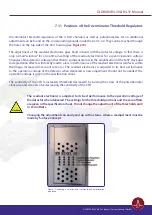
7.1.1 Positions of the Discriminator Threshold Regulators
Discriminator threshold regulators of the 4 DLD channels as well as potentiometers for an additional
adjustment can be found on the corresponding boards inside the ACU 3.4.2. They can be reached through
the holes on the top side of the ACU housing (see
).
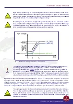
The adjustment of the readout electronics goes hand in hand with the detector voltage. In fact there is
only a small “window” for an optimum setting of the readout electronics for a given operation voltage.
Changes of the detector voltage, other than to compensate loss in the amplification of the MCP stack due
to degradation effects, will directly lead to a loss in performance of the readout electronics (artifacts within
the image, increased dark count rate etc.). The readout electronics is adjusted to its best performance
to the operation voltage of the detector when delivered. A new adjustment should not be needed. The
operation voltage is given in the specification sheet.
The sensitivity of the CFD is increased (threshold decreased) by turning the screw of the potentiometer
clockwise and vice versa for decreasing the sensitivity of the CFD.
The readout electronics is adjusted to its best performance to the operation voltage of
the detector when delivered. The settings for the threshold positions and the zero offsets
are given in the specification sheet.
Do not change the adjustment of the thresholds and/
or zero offsets.
Changing the adjustment can easily end up with a status, where a readjustment must be
made by Surface Concept.
Figure 13: Labeling of discriminator threshold and amplification
regulators.
DLD8080 R4.30 & R4.31 Manual | Surface Concept GmbH