SureCall, Inc | 1-888-365-6283 | [email protected] | www.surecall.com
11
Installation
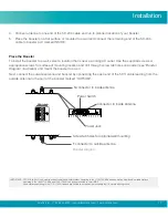
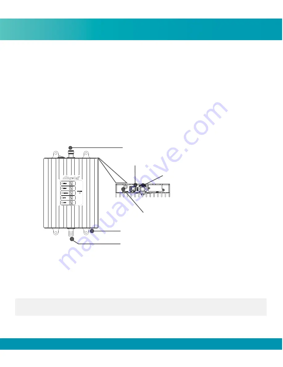
Power Jack
Power Switch
Connector to Inside Antenna
N connector to inside antenna
F connector to outside antenna
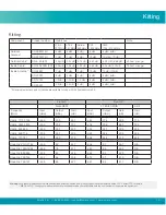
44
OFF
54
64
44
OFF
54
64
45
OFF
55
65
52
OFF
62
72
51
OFF
61
71
Screw tab holes for optional wall mounting
Booster Diagram
4. Connect antenna to one end of the SC-240 cable and run to planned location of your booster
5. Place the booster on a flat surface or mounted to a wall and connect the remaining end of the SC-240
cable to booster port marked INSIDE.
Place the Booster
To install the booster to a wall, select a location that is near a working AC outlet. Use the supplied screws or
appropriate screws for surface of mounting location and drill through screw tab holes on booster (see
“
Booster
Diagram”
illustration) and mount the booster to a wall.
Next, connect the outside antenna and booster by connecting the open end of the 50 ft. cable leading from the
outside antenna to the port of the booster marked “OUTSIDE”.
IMPORTANT:: FCC 27.5 (d)(4): Fixed, mobile, and portable (hand-held) stations operating in the 1710-1755 MHz band as well as mobile and portable stations
operating in the 1695-1710 MHz and 1755-1780 MHz bands are limited to 1 watt EIRP.
Fixed stations operating in the 1710-1755 MHz band are limited to a maximum antenna height of 10 meters above ground.


