background image

2-36

             X9DRW-3F/X9DRW-iF Motherboard User’s Manual

SP1

JPW3

JPW2

JPW4

JPB1

FAN2

FAN1

FAN4

FANA

FAN3

JPI2C1

LED3

LED1

COM2

JT

AG OF CPLD

SXB1A

SXB1B: CPU PCI-E 3.0 x16 + x16

P1-DIMMC1

CPU1

P1-DIMMC2

P1-DIMMD2

P1-DIMMD1

UID

SXB2: CPU2 PCI-E3.0 X16

LAN2

CPU2

LAN1

P1-DIMMB2

P1-DIMMA1

P1-DIMMA2

P1-DIMMB1

USB2/3

USB0/1

IPMI-LAN

P2-DIMMH1

P2-DIMMG2

P2-DIMMH2

P2-DIMMG1

COM1

P2-DIMMF2

P2-DIMMF1

P2-DIMME2

P2-DIMME1

X9DRW-3F/iF 

Rev.1.02

VGA

LAN

CTRL

BIOS

BMC

CTRL

JPW1

PHY

JPL1

B1

B2

A1 A2

B1

B2

A1 A2

SXB1C

JVRM_I2C2

JVRM_I2C1

JPG1

JIPMB1

JSTBY1

JSD1

JD1

JI2C1

JI2C2

JL1

JF1

I-SA
TA1

I-SA
TA0

JLPC1

JSM1

JSM2

T-SGPIO1

T-SGPIO2

I-SA
TA3

I-SA
TA2

I-SA
TA5

I-SA
TA4

JBAT1

JPME2

JWD1

JPME1

JP3

FANB

1

LED2

SATA/

USB4/5

PCH

JBT1

SCU0~3

SATA/SCU4~7

JVR1

JUIDB

JOH1

JWP1

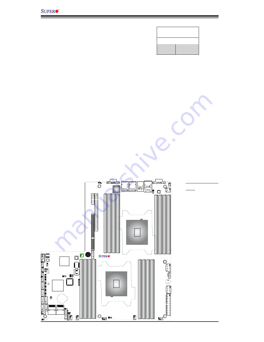
BMC Heartbeat LED

Status

Color/State        Definition     

Green:

Blinking

BMC: Normal

A

BMC Heartbeat LED

A BMC Heartbeat LED is located at LED1 
on the motherboard. When LED1 is blink-
ing, BMC functions normally. See the 
table at right for more information.

A. BMC Heartbeat  
LED 

Содержание X9DRW-3F

Страница 1: ...USER S MANUAL Revision 1 0 X9DRW 3F X9DRW iF...

Страница 2: ...DAMAGES IN PARTICULAR SUPER MICRO COMPUTER INC SHALL NOT HAVE LIABILITY FOR ANY HARDWARE SOFTWARE OR DATA STORED OR USED WITH THE PRODUCT INCLUDING THE COSTS OF REPAIRING REPLACING INTEGRATING INSTAL...

Страница 3: ...rformance for 1U 2U servers This motherboard is ideal for high end server platforms Please refer to our Website http www supermicro com for processor and memory support updates Manual Organization Cha...

Страница 4: ...aution Instructions to be strictly followed to prevent catastrophic system failure or bodily injury Warning Important information given to ensure proper system installation or to avoid damaging the co...

Страница 5: ...Micro Computer B V Het Sterrenbeeld 28 5215 ML s Hertogenbosch The Netherlands Tel 31 0 73 6400390 Fax 31 0 73 6416525 Email sales supermicro nl General Information support supermicro nl Technical Su...

Страница 6: ...2 2 Installing a Passive CPU Heatsink 2 6 Removing the Passive Heatsink 2 6 2 3 Installing and Removing the Memory Modules 2 7 Installing Removing DIMMs 2 7 Removing Memory Modules 2 8 2 4 Motherboard...

Страница 7: ...Power Connector 2 26 Power SMB I2 C Connector 2 27 IPMB 2 27 T SGPIO 1 2 Headers 2 28 DOM Power Connector 2 28 Power LED Speaker 2 29 2 7 Jumper Settings 2 30 Explanation of Jumpers 2 30 GLAN Enable D...

Страница 8: ...Frequently Asked Questions 3 7 3 5 Returning Merchandise for Service 3 8 Chapter 4 BIOS 4 1 Introduction 4 1 Starting BIOS Setup Utility 4 1 4 2 Main Setup 4 2 4 3 Advanced Setup Configurations 4 3 4...

Страница 9: ...Please check that the following items have all been included with your motherboard If anything listed here is damaged or missing contact your retailer The following items are included in the retail b...

Страница 10: ...therboard Image Note All graphics shown in this manual were based upon the latest PCB Revision available at the time of publishing of the manual The motherboard you ve received may or may not look exa...

Страница 11: ...PW3 JPW2 JPW4 JPB1 FAN2 FAN1 FAN4 FANA FAN3 JPI2C1 LED3 LED1 COM2 JTAG OF CPLD SXB1A SXB1B CPU PCI E 3 0 x16 x16 P1 DIMMC1 CPU1 P1 DIMMC2 P1 DIMMD2 P1 DIMMD1 UID SXB2 CPU2 PCI E3 0 X16 LAN2 CPU2 LAN1...

Страница 12: ...JOH1 P2 DIMMF2 P2 DIMMF1 P2 DIMME2 P2 DIMME1 X9DRW 3F X9DRW iF Jumpers Jumper Description Default Setting JBT1 Clear CMOS See Chapter 3 JI2 C1 JI2 C2 SMB to PCI E Slots Open Normal JPB1 BMC Enable Pi...

Страница 13: ...Device_On_Module Power Connector JSTBY1 Standby Power Connector LAN1 2 G bit Ethernet Ports 1 2 IPMI LAN IPMI_Dedicated LAN SATA SCU 0 3 4 7 Serial_Link SATA SCU Connections 0 3 4 7 for X9DRW 3F SCU...

Страница 14: ...pply connectors to the 24 pin power connector JPW1 two 8 pin power connectors JPW2 JPW3 and the 4 pin power connector JPW4 on the motherboard Failure in doing so will void the manufacturer warranty on...

Страница 15: ...ase refer to our Website at http www su permicro com products motherboard DIMM sizes RDIMM 1GB 2GB 4GB 8GB 16GB and 32GB 1 35V 1 5V Virtualization VT x VT d and VT c Chipset Intel PCH 606 602 Chipset...

Страница 16: ...s USB 4 5 BIOS 16 MB AMI BIOS Flash EEPROM APM 1 2 PCI 2 3 ACPI 1 0 2 0 3 0 4 0 USB Key board Plug Play PnP and SMBIOS 2 3 Power ACPI ACPM Power Management Management Main switch override mechanism Po...

Страница 17: ...m Environment Configuration Interface 2 0 support System resource alert via SuperDoctor III Dual Cooling Zones Thermal Monitor 2 TM2 support PECI Platform Environment Configuration Interface support S...

Страница 18: ...DIMM B DDR3 DIMM D C H F E Socket 00 Socket 01 1 2 1 2 1 2 1 2 1 2 1 2 P0 P0 P1 P1 x1 x16 x16 x16 J1 Right Slot PCIE 3 0x16 DMI PE3 PE2 PE1 QPI QPI CPU Front DMI PE1 PE2 PE3 P0PE3 J3 Left Slot PCIE 3...

Страница 19: ...interface with a transfer speed of up to 8 0 GT s providing superb system performance The PCH C606 C602 chipset provides extensive IO support including the follow ing functions and capabilities PCI Ex...

Страница 20: ...adjust the voltage thresholds to define the sensitivity of the voltage monitor Fan Status Monitor with Firmware Control The PC health monitor chip can check the RPM status of a cooling fan The onboar...

Страница 21: ...Systems Slow Blinking LED for Suspend State Indicator When the CPU goes into a suspend state the chassis power LED will start blinking to indicate that the CPU is in suspend mode When the user presse...

Страница 22: ...rd includes the following Intel Intelligent Power Node Manager NM Available when the NMView utility is installed in the system The Intel Intelligent Power Node Manager IPNM provides your system with r...

Страница 23: ...BMC supports VGA Graphic Cores for remote video displaying and editing It also provides a video data compressor for Keyboard Video Mouse KVM support if keyboard mouse are installed in the system With...

Страница 24: ...1 16 X9DRW 3F X9DRW iF Motherboard User s Manual Notes...

Страница 25: ...ng the board from the antistatic bag Handle the board by its edges only do not touch its components peripheral chips memory modules or gold contacts When handling chips or modules avoid touching their...

Страница 26: ...e sure that you use an Intel certified multi directional heatsink only Make sure to install the system board into the chassis before you install the CPU heatsink When receiving a server board without...

Страница 27: ...ng position 2 With the lever labled Close 1st fully retracted gently push down on the Open 1st lever to open the load plate Lift the load plate to open it com pletely OPEN1st WARNING OPEN1st WARNING 1...

Страница 28: ...the socket Do not drop the CPU on the socket Do not move the CPU horizontally or vertically Do not rub the CPU against the surface or against any pins of the socket to avoid damaging the CPU or the s...

Страница 29: ...load plate with the CPU inside the socket Lock the lever labeled Close 1st first then lock the lever labeled Open 1st Use your thumb to gently push the load levers down to the lever locks OPEN1st OPE...

Страница 30: ...Heatsink installation and removal please refer to the CPU Heatsink Instructions posted on our website at http www supermicro com support manuals Removing the Passive Heatsink Warning We do not recomm...

Страница 31: ...ling or removing DIMM modules to prevent any possible damage Installing Removing DIMMs 1 Insert the desired number of DIMMs into the memory slots starting with P1 DIMM A1 For best memory performance p...

Страница 32: ...ght down into the memory slot at the same time Notes 1 For proper memory installation be sure to install a DIMM module into the P2 DIMMG1 slot before inserting a 4 pin power connector into JPW4 as sho...

Страница 33: ...lation Configuration Table For memory to work proper please install DIMMs in pairs 1 CPU 2 DIMMs CPU1 P1 DIMMA1 P1 DIMMB1 1 CPU 4 DIMMs CPU1 P1 DIMMA1 P1 DIMMB1 P1 DIMMC1 P1 DIMMD1 1 CPU 5 8 DIMMs CPU...

Страница 34: ...ll DIMM modules in pairs with even number of DIMMs installed All channels in a system will run at the fastest common frequency Due to memory allocation to system devices the amount of memory that rema...

Страница 35: ...ffs click in or are screwed in tightly Then use a screwdriver to secure the motherboard onto the motherboard tray Tools Needed Phillips Screwdriver Pan head screws 7 pieces Standoffs 7 pieces if neede...

Страница 36: ...in the chassis as needed 5 Install the motherboard into the chassis carefully to avoid damaging mother board components 6 Using the Phillips screwdriver insert a Pan head 6 screw into a mounting hole...

Страница 37: ...See the picture below for the colors and locations of the various I O ports Back Panel Connectors and I O Ports Back Panel I O Port Locations and Definitions 1 COM Port 1 Turquoise 2 Back Panel USB Po...

Страница 38: ...1 JSM1 JSM2 T SGPIO1T SGPIO2 I SATA3 I SATA2 I SATA5 I SATA4 JBAT1 JPME2 JWD1 JPME1 JP3 FANB 1 LED2 SATA USB4 5 PCH JBT1 SCU0 3 SATA SCU4 7 JVR1 JUIDB JOH1 JWP1 Universal Serial Bus USB Four Universal...

Страница 39: ...erial Ports Two COM connections COM1 COM2 are located on the mother board COM1 is located on the Back plane I O panel COM2 located next to Front Accessible USB 4 5 is used to provide front access seri...

Страница 40: ...above USB 0 1 ports on the backplane provides KVM support for IPMI 2 0 All these ports accept RJ45 type cables Note Please refer to the LED Indicator Section for LAN LED information LAN Ports Pin Defi...

Страница 41: ...anel at JF1 Connect a cable to Pin 8 on JF1 for Front Panel UID LED indication When you press the UID switch both Rear UID LED and Front Panel UID LED Indicators will be turned on Press the UID switch...

Страница 42: ...I SATA3 I SATA2 I SATA5 I SATA4 JBAT1 JPME2 JWD1 JPME1 JP3 FANB 1 LED2 SATA USB4 5 PCH JBT1 SCU0 3 SATA SCU4 7 JVR1 JUIDB JOH1 JWP1 Front Control Panel JF1 contains header pins for various buttons an...

Страница 43: ...Power LED Pin Definitions JF1 Pin Definition 15 3 3V 16 PWR LED Front Control Panel Pin Definitions A NMI B PWR LED A B SP1 JPW3 JPW2 JPW4 JPB1 FAN2 FAN1 FAN4 FANA FAN3 JPI2C1 LED3 LED1 COM2 JTAG OF...

Страница 44: ...ns HDD LED Pin Definitions JF1 Pin Definition 13 3 3V Standby 14 HD Active A HDD LED B NIC1 Link LED C NIC1 Activity LED D NIC2 Link LED E NIC2 Activity LED GLAN1 2 LED Pin Definitions JF1 Pin Definit...

Страница 45: ...l UID LED indicator The Red LED takes precedence over the Blue LED by default Refer to the table on the right for pin definitions OH Fan Fail PWR Fail Blue_UID LED Pin Definitions JF1 Pin Definition 7...

Страница 46: ...et Button The Reset Button connection is located on pins 3 and 4 of JF1 Attach it to a hardware reset switch on the computer case Refer to the table on the right for pin definitions Reset Button Pin D...

Страница 47: ...WR JPW1 two 8 pin PWR connectors JPW2 JPW3 and the 4 pin PWR connector to the power supply Failure to do so will void the manufacturer warranty on your power supply and motherboard 2 6 Connecting Cabl...

Страница 48: ...3 SATA SCU4 7 JVR1 JUIDB JOH1 JWP1 A Fan 1 B Fan 2 C Fan 3 D Fan 4 E Fan A F Fan B G Chassis Intrusion Chassis Intrusion A Chassis Intrusion header is located at JL1 on the motherboard Attach an appro...

Страница 49: ...3 I SATA2 I SATA5 I SATA4 JBAT1 JPME2 JWD1 JPME1 JP3 FANB 1 LED2 SATA USB4 5 PCH JBT1 SCU0 3 SATA SCU4 7 JVR1 JUIDB JOH1 JWP1 A Internal Speaker Buzz er B OH LED Internal Speaker The Internal Speaker...

Страница 50: ...ED2 SATA USB4 5 PCH JBT1 SCU0 3 SATA SCU4 7 JVR1 JUIDB JOH1 JWP1 A Port 80 Header B Standby PWR Connector Port 80 Header A Port 80 header located at JLPC1 provides Port 80 support Port 80 is an Ask an...

Страница 51: ...JD1 JI2C1 JI2C2 JL1 JF1 I SATA1 I SATA0 JLPC1 JSM1 JSM2 T SGPIO1T SGPIO2 I SATA3 I SATA2 I SATA5 I SATA4 JBAT1 JPME2 JWD1 JPME1 JP3 FANB 1 LED2 SATA USB4 5 PCH JBT1 SCU0 3 SATA SCU4 7 JVR1 JUIDB JOH1...

Страница 52: ...M2 T SGPIO1T SGPIO2 I SATA3 I SATA2 I SATA5 I SATA4 JBAT1 JPME2 JWD1 JPME1 JP3 FANB 1 LED2 SATA USB4 5 PCH JBT1 SCU0 3 SATA SCU4 7 JVR1 JUIDB JOH1 JWP1 A B C A T SGPIO1 B T SGPIO2 C SATA DOM PWR T SGP...

Страница 53: ...I2C2 JL1 JF1 I SATA1 I SATA0 JLPC1 JSM1 JSM2 T SGPIO1T SGPIO2 I SATA3 I SATA2 I SATA5 I SATA4 JBAT1 JPME2 JWD1 JPME1 JP3 FANB 1 LED2 SATA USB4 5 PCH JBT1 SCU0 3 SATA SCU4 7 JVR1 JUIDB JOH1 JWP1 A PWR...

Страница 54: ...JPME2 JWD1 JPME1 JP3 FANB 1 LED2 SATA USB4 5 PCH JBT1 SCU0 3 SATA SCU4 7 JVR1 JUIDB JOH1 JWP1 2 7 Jumper Settings Explanation of Jumpers To modify the operation of the mother board jumpers can be use...

Страница 55: ...ct pads to prevent accidental clearing of CMOS To clear CMOS use a metal object such as a small screwdriver to touch both pads at the same time to short the connection Always remove the AC power cord...

Страница 56: ...1 I SATA0 JLPC1 JSM1 JSM2 T SGPIO1T SGPIO2 I SATA3 I SATA2 I SATA5 I SATA4 JBAT1 JPME2 JWD1 JPME1 JP3 FANB 1 LED2 SATA USB4 5 PCH JBT1 SCU0 3 SATA SCU4 7 JVR1 JUIDB JOH1 JWP1 A VGA Enabled B BMC Enabl...

Страница 57: ...PHY JPL1 B1 B2 A1 A2 B1 B2 A1 A2 SXB1C JVRM_I2C2 JVRM_I2C1 JPG1 JIPMB1 JSTBY1 JSD1 JD1 JI2C1 JI2C2 JL1 JF1 I SATA1 I SATA0 JLPC1 JSM1 JSM2 T SGPIO1T SGPIO2 I SATA3 I SATA2 I SATA5 I SATA4 JBAT1 JPME2...

Страница 58: ...n to the Gigabit Ethernet ports an IPMI Dedicated LAN is also located above the Backplane USB ports 0 1 on the motherboard The amber LED on the right indicates activity while the green LED on the left...

Страница 59: ...1 LED2 SATA USB4 5 PCH JBT1 SCU0 3 SATA SCU4 7 JVR1 JUIDB JOH1 JWP1 Onboard Power LED An Onboard Power LED is located at LED2 on the motherboard When this LED is on the system is on Be sure to turn o...

Страница 60: ...X9DRW 3F iF Rev 1 02 VGA LAN CTRL BIOS BMC CTRL JPW1 PHY JPL1 B1 B2 A1 A2 B1 B2 A1 A2 SXB1C JVRM_I2C2 JVRM_I2C1 JPG1 JIPMB1 JSTBY1 JSD1 JD1 JI2C1 JI2C2 JL1 JF1 I SATA1 I SATA0 JLPC1 JSM1 JSM2 T SGPIO1...

Страница 61: ...A USB4 5 PCH JBT1 SCU0 3 SATA SCU4 7 JVR1 JUIDB JOH1 JWP1 Note For more information on SATA HostRAID configuration please refer to the Intel SATA HostRAID User s Guide posted on our Website http www s...

Страница 62: ...2 38 X9DRW 3F X9DRW iF Motherboard User s Manual Notes...

Страница 63: ...otherboard and chassis 2 Disconnect all ribbon wire cables from the motherboard including those for the keyboard and mouse if any 3 Remove all add on cards 4 Install CPU 1 first making sure it is full...

Страница 64: ...gs by unplugging the power cord and contracting both pads on the CMOS Clear Jumper JBT1 Refer to Section 2 7 in Chapter 2 2 Remove all components from the motherboard especially the DIMM mod ules Make...

Страница 65: ...seated in their slots Follow the instructions given in Section 2 3 in Chapter 2 6 Please follow the instructions given in the DIMM Population Tables listed in Section 2 3 to install your memory modul...

Страница 66: ...orking properly 3 Using minimum configuration for troubleshooting Remove all unnecessary components starting with add on cards first and use minimum configuration with a CPU and a memory module instal...

Страница 67: ...ons in this chapter or see the FAQs on our website http www supermicro com before contacting Technical Support 2 BIOS upgrades can be downloaded from our website http www supermicro com 3 If you still...

Страница 68: ...used batteries carefully Do not damage the bat tery in any way a damaged battery may release hazardous materials into the environment Do not discard a used battery in the garbage or a public landfill...

Страница 69: ...how to update your BIOS on our website Select your motherboard model and download the BIOS file to your computer Also check the current BIOS revision to make sure that it is newer than your BIOS befo...

Страница 70: ...your used battery properly 3 5 Returning Merchandise for Service A receipt or copy of your invoice marked with the date of purchase is required before any warranty service will be rendered You can obt...

Страница 71: ...ns cannot be configured Options in blue can be configured by the user The right frame displays the key legend Above the key legend is an area reserved for a text message When an option is selected in...

Страница 72: ...re 4 2 Main Setup When you first enter the AMI BIOS Setup utility you will enter the Main setup screen You can always return to the Main setup screen by selecting the Main tab on the top of the screen...

Страница 73: ...es sages and the OEM logo Select Disabled to display the POST messages Select Enabled to display the OEM logo instead of the normal POST messages The op tions are Enabled and Disabled AddOn ROM Displa...

Страница 74: ...than 5 minutes The options are Enabled and Disabled Power Button Function If this feature is set to Instant Off the system will power off immediately as soon as the user presses the power button If th...

Страница 75: ...ed in Socket 1 Socket 2 64 bit This item indicates if the CPU installed in Socket 1 or Socket 2 supports 64 bit technology Clock Spread Spectrum Select Enable to enable Clock Spectrum support which wi...

Страница 76: ...sites for more information Intel AES NI Select Enable to use the Intel Advanced Encryption Standard AES New Instruc tions NI to ensure data security The options are Enabled and Disabled Hardware Pref...

Страница 77: ...t and Custom If the option is set to Custom the following items will display EIST Available when Power Technology is set to Custom EIST Enhanced Intel SpeedStep Technology allows the system to au toma...

Страница 78: ...tate package register The options are C0 C2 C6 and No Limit Factory Long Duration Power Limit This item displays the power limit set by the manufacturer during which long duration power is maintained...

Страница 79: ...cantly reduces CPU over head by leveraging CPU architectural improvements freeing the system resource for other tasks The options are Disabled and Enabled DCA Support Select Enabled to use Intel s DCA...

Страница 80: ...speed for QPI Link connections The options are Fast and Slow QPI Link Frequency Select Use this feature to select the desired QPI frequency The options are Auto 6 4 GT s 7 2 GT s and 8 0 GT s DIMM Con...

Страница 81: ...es mechanisms to enforce power consumption limits on supported processors The options are Disabled DRAM RAPL MODE0 and DRAM RAPL MODE1 DDR Speed Use this feature to force a DDR3 memory module to run a...

Страница 82: ...data security and integrity The options are Disabled and Enabled Device Tagging Select Enabled to support device tagging The options are Disabled and En abled Thermal Throttling Throttling improves r...

Страница 83: ...nd Off This item is for operating systems that do not support Enhanced Host Controller Interface EHCI hand off When enabled EHCI ownership change will be claimed by the EHCI driver The options are Dis...

Страница 84: ...options are Enabled and Disabled RAID Mode The following items are displayed when RAID Mode is selected Port 0 5 Hot Plug Select Enabled to enable hot plug support for the particular port The options...

Страница 85: ...CI E device to enhance system performance The options are Auto 128 Bytes 256 Bytes 512 Bytes 1024 Bytes 2048 Bytes and 4096 Bytes Maximum Read Request Select Auto to allow the system BIOS to automatic...

Страница 86: ...boot device The options are Onboard and Offboard Network Stack Select Enabled enable PXE Preboot Execution Environment or UEFI Unified Extensible Firmware Interface for network stack support The opti...

Страница 87: ...and SOL COM 2 These two submenus allow the user to configure the following Console Redirection settings for a COM Port selected by the user Console Redirection Select Enabled to use a COM Port select...

Страница 88: ...sent along with the data bits Select Space to add a Space as a parity bit to be sent with your data bits The options are None Even Odd Mark and Space Stop Bits A stop bit indicates the end of a seria...

Страница 89: ...Configuration and Power Interface ACPI power management settings for your system ACPI Sleep State Use this feature to select the ACPI State when the system is in sleep mode Select S1 CPU_Stop_Clock to...

Страница 90: ...t Status Information This item displays the information regarding the current TPM status TPM Enable Status This item displays the status of TPM Support to indicate if TPM is currently enabled or disab...

Страница 91: ...hnology support TPM Support Trusted Platform support TPM State Trusted Platform state Intel ME Subsystem Configuration This feature displays the following ME Subsystem Configuration settings ME BIOS I...

Страница 92: ...The Options are AutoNeg Auto Negotiation 10 Mbps Half 10 Mbps Full 100 Mbps Half and 10 Mbps Full Wake On LAN WOL Select Enabled to wake up the system with a device a magic packet The op tions are Di...

Страница 93: ...S System Management BIOS Event Logging during system boot The options are Enabled and Disabled Runtime Error Logging Support Select Enabled to support Runtime Error Logging The options are Enabled and...

Страница 94: ...em boot events The options are Disabled and Enabled MECI Multiple Event Count Increment Enter the increment value for the multiple event counter Enter a number between 1 to 255 The default setting is...

Страница 95: ...ed in your system System Event Log Enabling Disabling Options SEL Components Select Enabled for all system event logging at bootup The options are Enabled and Disabled Erasing Settings Erase SEL Selec...

Страница 96: ...ption is set to Yes BIOS will configure the following settings to IPMI at next system boot Configuration Address Source This feature allows the user to select the source of the IP address for this com...

Страница 97: ...SM which provides compatibility support for traditional legacy BIOS for system boot The op tions are Enabled Disabled and Auto Boot Option Priorities Boot Option 1 Boot Option 4 This item allows the u...

Страница 98: ...e options are Select One to Delete and UEFI Built in EFI Shell 4 6 Security This menu allows the user to configure the following security settings for the system Administrator Password Use this featur...

Страница 99: ...nd Reset When you have completed the system configuration changes select this option to save the changes and reboot the computer so that the new system configuration settings can take effect Select Sa...

Страница 100: ...as User Defaults Select this feature and press Enter to save the current settings as the user s defaults When the dialog box appears asking you if you want to save values as user s defaults click Yes...

Страница 101: ...hould consult with your system manufacturer for possible repairs These fatal errors are usually communicated through a series of audible beeps The numbers on the fatal error list correspond to the num...

Страница 102: ...A 2 X9DRW 3F X9DRW iF Motherboard User s Manual Notes...

Страница 103: ...storage driver diskette by booting into a Driver CD please set the SATA Configuration to Compatible Mode and configure SATA as IDE in the BIOS Setup After making the driver diskette be sure to change...

Страница 104: ...Doctor III displays crucial system information such as CPU temperature system voltages and fan status See the Figure below for a display of the SuperDoctor III interface Note 1 The default user name a...

Страница 105: ...r III Interface Display Screen II Remote Control The SDIII utility and the user guide can be downloaded from our web site at http www supermicro com products accessories software SuperDoctorIII cfm Fo...

Страница 106: ...B 4 X9DRW 3F X9DRW iF Motherboard User s Manual Notes...

Страница 107: ...expected to result in significant injury or loss of life or catastrophic property damage Accordingly Supermicro disclaims any and all liability and should buyer use or sell such products for use in su...

Отзывы: