background image

B-3

Appendix B: System Specifications

Notes

Содержание SUPERSERVER 1027TR-TF

Страница 1: ...SUPER SUPERSERVER 1027TR TF SUPERSERVER 1027TR TFF SUPERSERVER 1027TR TQF USER S MANUAL Revision 1 0...

Страница 2: ...any such disputes Super Micro s total liability for all claims will not exceed the price paid for the hardware product FCC Statement This equipment has been tested and found to comply with the limits...

Страница 3: ...main components included with the server system and describes the main features of the Super X9DRT F X9DRT IBFF X9DRT IBQF serverboard and the CSE 809BTS 1K28BP chassis Chapter 2 Server Installation T...

Страница 4: ...f connectors headers and jump ers Refer to this chapter when adding or removing processors or main memory and when reconfiguring the serverboard Chapter 6 Advanced Chassis Setup Refer to Chapter 6 for...

Страница 5: ...em Power 1 5 SATA Subsystem 1 5 Control Panel 1 5 Rear I O Panel 1 5 Cooling System 1 5 1 4 1U Twin System Notes 1 6 System Power 1 6 SATA Backplane Drives 1 6 1 5 Contacting Supermicro 1 7 Chapter 2...

Страница 6: ...4 Drive Carrier LEDs 3 3 Chapter 4 Standardized Warning Statements for AC Systems 4 1 About Standardized Warning Statements 4 1 Warning Definition 4 1 Installation Instructions 4 4 Circuit Breaker 4...

Страница 7: ...X9DRT IBFF X9DRT IBQF Quick Reference 5 15 5 9 Connector Definitions 5 16 5 10 Jumper Settings 5 23 5 11 Onboard Indicators 5 25 5 12 PCI Express and Serial ATA Connections 5 26 5 13 Installing Additi...

Страница 8: ...tion Data 7 1 Starting the Setup Utility 7 2 7 2 Main Setup 7 2 7 3 Advanced Setup Configurations 7 3 7 4 Event Logs 7 25 7 5 IPMI 7 28 7 6 Boot 7 30 7 7 Security 7 31 7 8 Save Exit 7 32 Appendix A BI...

Страница 9: ...shroud MCP 310 80803 0B SATA Accessories Eight SATA hard drive carriers MCP 220 00047 0B One internal SATA backplane BPN SAS 809TQ O P Two 59 cm SATA cables CBL 0207L Two 43 cm SATA cables CBL 0226L...

Страница 10: ...system or 64 GB of unbuffered ECC Non ECC 800 1066 1333 1600 SDRAM 256 GB for the system See Chapter 5 Section 6 for more details on installing memory into the system Onboard Serial ATA An on chip SA...

Страница 11: ...ated in Nuvoton WPCM450 BMC controller Other Features Other onboard features that promote system health include voltage monitors auto switching voltage regulators chassis and CPU overheat sensors viru...

Страница 12: ...PEG1_4 1 PEG1_8 PCI 32bit USB LAN I350 2 ports AT25321 IB FDR QDR LPC CPU FRONT FAN Side CPU REAR I O Side USB REAR Type A 0 1 2 H F E Socket 1 Socket 2 1 P0 P0 P1 P1 PE3 PE2 PE1 DMI PE3 PE2 PE1 DMI...

Страница 13: ...ontrol panels associated with each node serverboard Each control panel has LEDs to indicate power on net work activity hard disk drive activity and system overheat conditions Each control panel also i...

Страница 14: ...he I2 C signals used for power supply monitoring are received by the primary serverboard only When viewed from the front of the chassis the serverboard on the left is referred to as the primary board...

Страница 15: ...s Super Micro Computer B V Het Sterrenbeeld 28 5215 ML s Hertogenbosch The Netherlands Tel 31 0 73 6400390 Fax 31 0 73 6416525 Email sales supermicro nl General Information support supermicro nl Techn...

Страница 16: ...1 8 SUPERSERVER 1027TR TF 1027TR TFF 1027TR TQF User s Manual Notes...

Страница 17: ...tion for the rack unit that will hold the 1027TR TF 1027TR TFF 1027TR TQF It should be situated in a clean dust free area that is well ventilated Avoid areas where heat electrical noise and electromag...

Страница 18: ...he rack In multiple rack installations the racks should be coupled together Always make sure the rack is stable before extending a component from the rack You should extend only one component at a tim...

Страница 19: ...a ture Tmra Reduced Airflow Equipment should be mounted into a rack so that the amount of airflow required for safe operation is not compromised Mechanical Loading Equipment should be mounted into a r...

Страница 20: ...ved two rack rail assemblies in the rack mounting kit Each assembly consists of two sections an inner fixed chassis rail that secures directly to the server chassis and an outer fixed rack rail that s...

Страница 21: ...terfere with normal use of the chassis if you decide not to use a server rack Attach the inner rail extensions to to the inner rails to stabilize the chassis within the rack Installing the Inner Rail...

Страница 22: ...bracket to the outside of the long bracket You must align the pins with the slides Also both bracket ends must face the same direction 2 Adjust both the short and long brackets to the proper distance...

Страница 23: ...rail extensions B Also confirm that the outer rails C are installed on the rack 2 Align the chassis rails extentions B with the front of the rack rails C 3 Slide the chassis rail extensions into the...

Страница 24: ...f a bezel is included on your server remove it Then at tach the two front brackets to each side of the chassis then the two rear brackets positioned with just enough space to accommodate the width of...

Страница 25: ...e system from the rack completely depress the locking tabs in the chassis rails push the right side tab down and the left side tab up to continue to pull the system out past the locked position Checki...

Страница 26: ...stall SATA drives please refer to Chapter 6 Checking the Airflow 1 Airflow is provided by six sets of 4 cm PWM fans each set of fans consists of two fans that are mounted back to back and an air shrou...

Страница 27: ...Chapter 2 Server Installation 2 11 Figure 2 5 Accessing the Inside of the System Remove these screws Remove this screw Remove this screw 1 1 1 2 1 3 1 1 1 4...

Страница 28: ...ntly of the other 3 2 Control Panel Buttons There are two push buttons located on each control panel a reset button and a power on off button UID Depressing the UID unit identifier button illuminates...

Страница 29: ...overheat condition which may be caused by cables obstructing the airflow in the system or the ambient room temperature being too warm Check the routing of the cables and make sure all fans are present...

Страница 30: ...een LED on the front of the drive carrier indi cates drive activity A connection to the hard drive backplane enables this LED to blink on and off when that particular drive is being accessed Red The r...

Страница 31: ...3 4 SUPERSERVER 1027TR TF 1027TR TFF 1027TR TQF User s Manual Notes...

Страница 32: ...nt for assistance Only certified technicians should attempt to install or configure components Read this appendix in its entirety before installing or configuring components in the Supermicro chassis...

Страница 33: ...er equipo considere los riesgos de la corriente el ctrica y familiar cese con los procedimientos est ndar de prevenci n de accidentes Al final de cada advertencia encontrar el n mero que le ayudar a e...

Страница 34: ...l kan veroorzaken Voordat u aan enige apparatuur gaat werken dient u zich bewust te zijn van de bij een elektrische installatie betrokken risico s en dient u op de hoogte te zijn van de standaard proc...

Страница 35: ...dem Anschlie en des Systems an die Stromquelle die Installationsanweisungen lesen Advertencia Lea las instrucciones de instalaci n antes de conectar el sistema a la red de alimentaci n Attention Avant...

Страница 36: ...ert ist Stellen Sie sicher dass der Nennwert der Schutzvorrichtung nicht mehr als 250 V 20 A betr gt Advertencia Este equipo utiliza el sistema de protecci n contra cortocircuitos o sobrecorrientes de...

Страница 37: ...m zur ckgreift um Systemsbestandteile anzubringen oder zu entfernen Warning The system must be disconnected from all sources of power and the power cord removed from the power supply module s before a...

Страница 38: ...nentes de sistema Attention Le syst me doit tre d branch de toutes les sources de puissance ainsi que de son cordon d alimentation secteur avant d acc der l int rieur du chassis pour installer ou enle...

Страница 39: ...uipment Warnung Das Installieren Ersetzen oder Bedienen dieser Ausr stung sollte nur geschultem qualifiziertem Personal gestattet werden Advertencia Solamente el personal calificado debe instalar reem...

Страница 40: ...stallation in Bereichen mit beschr nktem Zutritt vorgesehen Der Zutritt zu derartigen Bereichen ist nur mit einem Spezialwerkzeug Schloss und Schl ssel oder einer sonstigen Sicherheitsvorkehrung m gli...

Страница 41: ...with the same or equivalent type recommended by the manufacturer Dispose of used batteries according to the manufacturer s instructions Waarschuwing Dit apparaat is bedoeld voor installatie in gebiede...

Страница 42: ...ecommand e par le fabricant Jeter les piles usag es conform ment aux instructions du fabricant Advertencia Existe peligro de explosi n si la bater a se reemplaza de manera incorrecta Reemplazar la bat...

Страница 43: ...a conexi n para fuentes de alimentaci n Para cortar por completo el suministro de energ a deben desconectarse todas las conexiones Attention Cette unit peut avoir plus d une connexion d alimentation P...

Страница 44: ...ero es peligroso Tenga cuidado cuando lo revise Attention Lorsque le syst me est en fonctionnement des tensions lectriques circulent sur le fond de panier Prendre des pr cautions lors de la maintenanc...

Страница 45: ...national electrical codes Warnung Die Installation der Ger te muss den Sicherheitsstandards entsprechen Advertencia La instalacion del equipo debe cumplir con las normas de electricidad locales y naci...

Страница 46: ...ional laws and regulations Attention L quipement doit tre install conform ment aux normes lectriques nationales et locales Waarschuwing Bij installatie van de apparatuur moet worden voldaan aan de lok...

Страница 47: ...ducto debe seguir todas las leyes y reglamentos nacionales Attention La mise au rebut ou le recyclage de ce produit sont g n ralement soumis des lois et ou directives de respect de l environnement Ren...

Страница 48: ...dedos los destornilladores y todos los objetos lejos de las aberturas del ventilador Attention Il est possible que les ventilateurs soient toujours en rotation lorsque vous retirerez le bloc ventilat...

Страница 49: ...abel und Adapter kann zu einer Fehlfunktion oder ein Brand entstehen Elektrische Ger te und Material Safety Law verbietet die Verwendung von UL oder CSA zertifizierte Kabel UL oder CSA auf der Code f...

Страница 50: ...utres appareils lectriques que les produits d sign s par Supermicro seulement AC AC UL CSA UL CSA UL CSA Supermicro UL CSA AC Electrical Appliance and Material Safety Law UL CSA UL CSA Waarschuwing Bi...

Страница 51: ...4 20 SUPERSERVER 1027TR TF 1027TR TFF 1027TR TQF User s Manual Notes...

Страница 52: ...ant to handle them very carefully see previous chapter To prevent the X9DRT F X9DRT IBFF X9DRT IBQF serverboard from bending keep one hand under the center of the board to support it when handling The...

Страница 53: ...top cover from the chassis to gain full access to the inside of the server If already installed in a rack grasp the two handles on either side and pull the unit straight out until the rails lock into...

Страница 54: ...ach connection listed should be made for both serverboards in the chassis SATA drive cables SATA0 SATA3 Control Panel cable JF1 Connecting Power Cables The X9DRT F X9DRT IBFF X9DRT IBQF has two 20 pin...

Страница 55: ...gure 5 2 I O Ports NMI x Key 3 3V Front UID Button NIC1 LED Activity NIC2 LED Activity UID LED 3 3V Reset Button Power Button 5V x Key Power On LED HDD LED NIC1 LED Link NIC2 LED Link OH Fan Fail Pwr...

Страница 56: ...dling the processor package avoid placing direct pressure on the label area of the fan Notes Always connect the power cord last and always remove it before adding re moving or changing any hardware co...

Страница 57: ...F User s Manual 1 Using your thumb and the index finger remove the WARNING plastic cap from the socket 2 Use your thumb and index finger to hold the CPU on its edges Align the CPU keys which are semi...

Страница 58: ...n one direction Make sure that it is properly inserted into the CPU socket before closing the load plate If it doesn t close properly do not force it as it may dam age your CPU Instead open the load p...

Страница 59: ...Manual Identifying a Heatsink Two types of heatsinks SNK P0047PW and SNK P0047PS are used in 1027TR TF 1027TR TFF 1027TR TQF Be careful with its own proper instal lation location See the figure below...

Страница 60: ...e the heatsink on top of the CPU so that the four mounting holes are aligned with those on the preinstalled heatsink reten tion mechanism 4 Screw in two diagonal screws i e the 1 and the 2 screws unti...

Страница 61: ...eatsink to loosen it from the CPU Do not use excessive force when wrig gling the heatsink 5 Once the heatsink is loose remove it from the CPU socket 6 To reinstall the CPU and the heatsink clean the s...

Страница 62: ...l DIMMs See tables below and on following pages CAUTION Exercise extreme care when installing or removing DIMM modules to prevent any possible damage Processors and their Corresponding Memory Modules...

Страница 63: ...or detailed information on memory support and updates please refer to the SMC Recommended Memory List posted on our website at http www supermicro com support resources mem cfm Installing RDIMM ECC Me...

Страница 64: ...y Support Ranks Per DIMM Data Width See the Note Below Memory Capacity Per DIMM Speed MT s and Voltage Validated by Slot per Channel SPC and DIMM Per Channel DPC 1 Slot Per Channel 1DPC 1 35V 1 5V QRx...

Страница 65: ...B LAN I350 2 ports AT25321 IB FDR QDR LPC CPU FRONT FAN Side CPU REAR I O Side USB REAR Type A 0 1 2 H F E Socket 1 Socket 2 1 P0 P0 P1 P1 PE3 PE2 PE1 DMI PE3 PE2 PE1 DMI Gen3 x16 x4 VGA BMC WPCM450 D...

Страница 66: ...DRT IBQF IBFF only JBAT1 Onboard Battery See Chpt 3 for Used Battery Disposal JF1 Front Panel Control Header JP8 4 Pin Auxiliary Power Connector See P 2 26 in Chpt 2 JIPMB1 4 pin External BMC I2C Head...

Страница 67: ...s input power supply at the same time Only one connector can be used for input power supply to the motherboard at a time For proper use of these proprietary PWR Connectors please customize your PWR ca...

Страница 68: ...8 of Front Control Panel to use the Over heat Fan Fail Power Fail and UID LED connections The Red LED on pin 7 pro vides warnings of overheat fan failure or power failure The Blue LED on pin 8 works...

Страница 69: ...d on pins 15 and 16 of JF1 This connec tion is used to provide LED indication of power being supplied to the system See the table on the right for pin definitions Power LED Pin Definitions JF1 Pin Def...

Страница 70: ...ion Pin Definition S1 Input Pair0 Pos S9 Output Pair3 Pos S2 Input Pair0 Neg S10 Output Pair3 Neg S3 Input Pair1 Pos S11 Output Pair2 Pos S4 Input Pair1 Neg S12 Output Pair2 Neg S5 Input Pair2 Pos S13...

Страница 71: ...PWR Fail 4 Ground 5 3 3V TPM Header Port 80 A Trusted Platform Module Port 80 head er is located at JTPM1 to provide TPM support and Port 80 connection Use this header to enhance system performance an...

Страница 72: ...2 P3V3SB 4 TD1 13 Link 100 LED Yellow 3V3SB 5 TD1 14 Link 1000 LED Yellow 3V3SB 6 TD2 15 Ground 7 TD2 16 Ground 8 TD3 17 Ground 9 TD3 18 Ground NC indicates no connection Universal Serial Bus USB Two...

Страница 73: ...vide easy identification of a system unit that may be in need of service See the table on the right for pin definitions Note UID LED is supported by the physical switch or the BMC When it is controlle...

Страница 74: ...so clear any passwords Instead of pins this jumper consists of contact pads to prevent accidentally clearing the contents of CMOS To Clear CMOS 1 First power down the system and unplug the power cord...

Страница 75: ...jumper settings BMC Enable Jumper Settings Jumper Setting Definition Pins 1 2 BMC Enable Default Pins 2 3 Normal IB Enable X9DRT IBQF IBFF Only Use Jumper JIB1 to enable or disable the onboard Infini...

Страница 76: ...ctivity LED GLAN Link Indicator LED Settings LED Color Definition Off 10 Mbps or No Connection Green 100 Mbps Amber 1 Gbps Link LED GLAN Activity Indicator Left LED Settings Color Status Definition Ye...

Страница 77: ...iBand IB LED Indicators LEB1 LEB2 are located on the motherboard The green LED LEB1 is InfiniBand Link LED The yellow LED LEB2 indicates activity Refer to the table on the right for details Also see t...

Страница 78: ...installing each item you must re boot the system before proceeding with the next item on the list The bottom icon with a CD on it allows you to view the entire contents of the CD 5 13 Installing Addi...

Страница 79: ...Supero Doctor III displays crucial system information such as CPU temperature system voltages and fan status See the Figure below for a display of the Supero Doctor III interface Notes The default Use...

Страница 80: ...vision 1 0 can be downloaded from our Web site at ftp ftp supermicro com utility Supero_Doctor_III You can also download SDIII User s Guide at http www supermicro com manuals other SDIII_User_Guide pd...

Страница 81: ...e below This battery must be replaced only with the same or an equivalent type recommended by the manufacturer CR2032 Dispose of used batteries according to the manufacturer s instructions Please hand...

Страница 82: ...Chapter 5 Advanced Serverboard Setup 5 31 Notes...

Страница 83: ...arefully The following measures are generally sufficient to protect your equipment from ESD discharge Precautions Use a grounded wrist strap designed to prevent static discharge Touch a grounded metal...

Страница 84: ...fy the connection Connect the cable from JF1 on the serverboard to the control panel PCB printed circuit board Make sure the red wire plugs into pin 1 on both connectors Pull all excess cabling out of...

Страница 85: ...are hot swappable There is no need to power down the system when switching fans Changing a System Fan Figure 6 3 1 If necessary open the chassis while the power is running to determine which fan has f...

Страница 86: ...ode Note the air shroud is intended for use with passive CPU heatsinks only When using active heatsinks you should remove the air shroud Installing the Air Shrouds Figure 6 4 1 Confirm that all six fa...

Страница 87: ...t swap capability of the SATA drives Figure 6 4 Installing the Air Shrouds Use caution when working around the SATA backplane Do not touch the backplane with any metal objects and make sure no cables...

Страница 88: ...the screw holes of both line up Note that there are holes in the carrier marked SATA to aid in correct installation 3 Secure the drive to the carrier with four screws as illustrated below 4 Insert th...

Страница 89: ...t units can be ordered directly from Supermicro see contact information in Chapter 1 Replacing the Power Supply Depress both main power buttons on the front of the chassis and then unplug the AC power...

Страница 90: ...the Power Supply Release Tab 4 Pull the power supply out using the handle provided 5 Push the new power supply module into the power bay until it clicks into place 6 Plug the AC power cord back into...

Страница 91: ...er The right frame displays the key legend Above the key legend is an area reserved for informational text When an option is selected in the left frame it is highlighted in white Often informational t...

Страница 92: ...consequential damage arising from a BIOS update If you have to update the BIOS do not shut down or reset the system while the BIOS is being updated to avoid possible boot failure 7 2 Main Setup When...

Страница 93: ...s system Build Date This item displays the date that the BIOS Setup utility was built Memory Information Total Memory This displays the amount of memory that is available in the system 7 3 Advanced Se...

Страница 94: ...y setting Select Force BIOS to use the Option ROM display mode set by the system BIOS The options are Force BIOS and Keep Current Bootup Num Lock Use this feature to set the Power on state for the Num...

Страница 95: ...power off immediately as soon as the user presses the power button If this feature is set to 4 Seconds Override the system will power off when the user presses the power button for 4 seconds or longer...

Страница 96: ...f the CPU installed in Socket 1 Socket 2 64 bit This item indicates if the CPU installed in Socket 1 or Socket 2 supports 64 bit technology Clock Spread Spectrum Select Enable to enable Clock Spectrum...

Страница 97: ...he processor or damage the system during an attack The default is Enabled Refer to Intel and Microsoft Web sites for more information Intel AES NI Select Enable to use the Intel Advanced Encryption St...

Страница 98: ...cient to support power saving mode Select Custom to cus tomize system power settings Select Disabled to disable power saving settings The options are Disabled Energy Efficient and Custom If the option...

Страница 99: ...um system performance with maximum cooling or maximum energy efficiency with maxi mum power saving The fan speeds are controlled by the firmware management via IPMI 2 0 The options are Performance Bal...

Страница 100: ...options are Enabled and Disabled Intel I OAT Select Enabled to enable Intel I OAT I O Acceleration Technology which sig nificantly reduces CPU overhead by leveraging CPU architectural improvements and...

Страница 101: ...IIO 2 PCIe ports to determine how the available PCI Express lanes to be distributed between the PCI Exp Root Ports QPI Configuration Current QPI Link Speed This item displays the current status of the...

Страница 102: ...rboard maintains two identical copies of all data in memory for data backup When Lock Step is selected the motherboard uses two areas of memory to run the same set of operations in parallel The defaul...

Страница 103: ...t allows the CPU to correct correctable memory errors found on a memory module When the CPU or I O issues a demand read command and the read data from memory turns out to be a correctable error the er...

Страница 104: ...ive Firmware Interface applications only The settings are Disabled Enabled and Auto Port 60 64 Emulation Select Enabled to enable I O port 60h 64h emulation support for the legacy USB keyboard so that...

Страница 105: ...ivity resumes The options are Enabled and Disabled Port 0 5 Hot Plug Select Enabled to enable hot plug support for a particular port which will allow the user to change a hardware component or device...

Страница 106: ...llow the system BIOS to automatically set the maximum payload value for a PCI E device to enhance system performance The options are Auto 128 Bytes and 256 Bytes Maximum Read Request Select Auto to al...

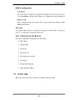
Страница 107: ...le PXE Preboot Execution Environment or UEFI Unified Extensible Firmware Interface for network stack support The options are Enabled and Disabled Super IO Configuration Super IO Chip This item display...

Страница 108: ...his option is set to Disabled the serial port becomes unavailable The options are Auto IO 3F8h IRQ 4 IO 3F8h IRQ 3 IO 2F8h IRQ 3 IO 3E8h IRQ 5 IO 2E8h IRQ 7 IO 3F8h IRQ 3 4 5 6 7 10 11 12 IO 2F8h IRQ...

Страница 109: ...is used in the host computer and the client computer A lower transmission speed may be required for long and busy lines The options are 9600 19200 38400 57600 and 115200 bits per second Data Bits Use...

Страница 110: ...nal resolution support The options are Dis abled and Enabled Legacy OS Redirection Resolution Use this feature to select the number of rows and columns used in Console Redirection for legacy OS suppor...

Страница 111: ...Select VT UTF8 to use UTF8 encoding to map Unicode characters into one or more bytes The options are ANSI VT100 VT100 and VT UTF8 Bits Per Second This item sets the transmission speed for a serial po...

Страница 112: ...riodic interrupts at a much higher frequency than a Real time Clock RTC does in synchronizing multimedia streams providing smooth playback reducing the de pendency on other timestamp calculation devic...

Страница 113: ...Status This item displays the status of TPM Ownership Intel TXT LT SX Configuration Intel TXT LT SX Hardware Support This feature indicates if the following hardware components support the Intel Trust...

Страница 114: ...rface Version ME Version iSCSI Configuration This item displays iSCSI configuration information iSCSI Initiator Name This item displays the name of the iSCSI Initiator which is a unique name used in t...

Страница 115: ...t The options are En abled and Disabled Blink LEDs This feature allows the user to specify the duration for LEDs to blink The range is from 0 15 seconds The default setting is 0 PORT CONFIGURATION INF...

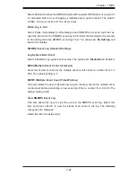
Страница 116: ...uring system boot The options are Enabled and Disabled Runtime Error Logging Support Select Enabled to support Runtime Error Logging The options are Enabled and Disabled Memory Correctable Error Thres...

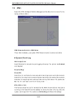
Страница 117: ...ard Settings Log System Boot Event Select Enabled to log system boot events The options are Disabled and Enabled MECI Multiple Event Count Increment Enter the increment value for the multiple event co...

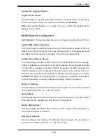
Страница 118: ...t system reboot Select Yes On every reset to erase all system event logs upon each system reboot Select No to keep all system event logs after each system reboot The options are No Yes On next reset a...

Страница 119: ...to know the IP address of this computer and enter it to the system manually in the field If DHCP is selected the BIOS will search for a DHCP Dynamic Host Configuration Protocol server in the network t...

Страница 120: ...riority Network Devices Hard Disk Drives The above options appear when detected by the BIOS Use these options to set the order of the legacy network and Hard Disk Drive devices detected by the motherb...

Страница 121: ...is required Select Setup to require the password only when entering setup Select Always to require the pass word when entering setup and on each boot The options are Setup and Always Administrator Pa...

Страница 122: ...nges Save Changes and Reset When you have completed the system configuration changes select this option to save the changes and reboot the computer so that the new system configuration settings can ta...

Страница 123: ...feature and press Enter to save the current settings as the user s defaults When the dialog box appears asking you if you want to save values as user s defaults select Yes to save the current values...

Страница 124: ...7 34 SUPERSERVER 1027TR TF 1027TR TFF 1027TR TQF User s Manual Notes...

Страница 125: ...e system to continue the boot up procedure If a fatal error occurs you should consult with your system manufac turer for possible repairs A 1 BIOS Error Beep Codes BIOS Error Beep Codes Beep Code LED...

Страница 126: ...A 2 SUPERSERVER 1027TR TF 1027TR TFF 1027TR TQF User s Manual Notes...

Страница 127: ...384 or 96 GB for the system Note interleaved memory requires DIMMs to be installed in pairs refer to Section 5 6 for details Serial ATA Controller Intel ICH10R on chip controller to support six 3 Gb s...

Страница 128: ...40 to 140 F Operating Relative Humidity 20 to 90 non condensing Non operating Relative Humidity 5 to 95 non condensing Regulatory Compliance Electromagnetic Emissions FCC Class A EN 55022 Class A EN...

Страница 129: ...B 3 Appendix B System Specifications Notes...

Страница 130: ...ilure to perform be reasonably expected to result in significant injury or loss of life or catastrophic property damage Accordingly Supermicro dis claims any and all liability and should buyer use or...

Отзывы: