background image

2-6

SC835 Chassis

 Manual

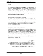
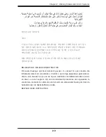
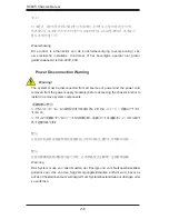
Power Disconnection Warning

 電源切断の警告

システムコンポーネントの取り付けまたは取り外しのために、シャーシー内部にアクセス

するには、

システムの電源はすべてのソースから切断され、電源コードは電源モジュールから取り

外す必要があります。

警告

在你打开机箱并安装或移除内部器件前,必须将系统完全断电,并移除电源线。

警告

在您打開機殼安裝或移除內部元件前,必須將系統完全斷電,並移除電源線。

Warnung 
Das System muss von allen Quellen der Energie und vom Netzanschlusskabel 
getrennt sein, das von den Spg.Versorgungsteilmodulen entfernt wird, bevor es 
auf den Chassisinnenraum zurückgreift, um Systemsbestandteile anzubringen oder 
zu entfernen.

 Warning!

The system must be disconnected from all sources of power and the power cord 
removed from the power supply module(s) before accessing the chassis interior to 
install or remove system components. 

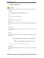
경고!

이 제품은 전원의 단락(과전류)방지에 대해서 전적으로 건물의 관련 설비에 
의존합니다. 보호장치의 정격이 반드시 250V(볼트), 20A(암페어)를 초과하지 
않도록 해야 합니다.

Waarschuwing 
Dit product is afhankelijk van de kortsluitbeveiliging (overspanning) van 
uw electrische installatie. Controleer of het beveiligde aparaat niet groter 
gedimensioneerd is dan 220V, 20A.

Содержание SC835TQ-R800B

Страница 1: ...SC835 Chassis Series SC835TQ R800B SC835TQ R920B SUPER USER S MANUAL 1 0c...

Страница 2: ...ED OR USED WITH THE PRODUCT INCLUDING THE COSTS OF REPAIRING REPLACING INTEGRATING INSTALLING OR RECOVERING SUCH HARDWARE SOFTWARE OR DATA Any disputes arising between manufacturer and customer shall...

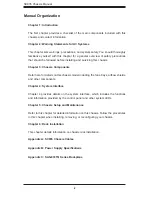
Страница 3: ...35 3U chassis features a unique and highly optimized design for dual core Xeon platforms The chassis is equipped with a redundant 800W high efficiency power supply High performance fans provide ample...

Страница 4: ...ents Refer here for details on this chassis model including the fans bays airflow shields and other components Chapter 4 System Interface Chapter 4 provides details on the system interface which inclu...

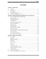
Страница 5: ...on Warning 2 6 Equipment Installation 2 8 Restricted Area 2 9 Battery Handling 2 10 Redundant Power Supplies 2 12 Backplane Voltage 2 13 Comply with Local and National Electrical Codes 2 14 Product Di...

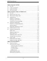
Страница 6: ...manent and Optional Standoffs 5 7 Standoff Labeling 5 7 Motherboard Installation Procedure 5 8 5 6 Installing Expansion Cards 5 9 5 7 Installing Cooling Elements 5 10 System Fans 5 11 Replacing a Syst...

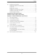
Страница 7: ...er Supply Specifications Appendix C SAS 833TQ Backplane Specifications C 1 ESD Safety Guidelines C 1 C 2 General Safety Guidelines C 1 C 3 An Important Note to Users C 2 C 4 Introduction to the SAS 83...

Страница 8: ...SC835 Chassis Manual viii Notes...

Страница 9: ...mplete list of safety warnings is provided on the Supermicro web site at http www supermicro com about policies safety_information cfm 1 2 Shipping List Part Numbers Please visit the following link fo...

Страница 10: ...ress Super Micro Computer B V Het Sterrenbeeld 28 5215 ML s Hertogenbosch The Netherlands Tel 31 0 73 6400390 Fax 31 0 73 6416525 Email sales supermicro nl General Information support supermicro nl Te...

Страница 11: ...ust be mailed when service is complete For faster service RMA authorizations may be requested online http www super micro com support rma Whenever possible repack the chassis in the original Supermicr...

Страница 12: ...SC835 Chassis Manual 1 4 Notes...

Страница 13: ...nt for assistance Only certified technicians should attempt to install or configure components Read this appendix in its entirety before installing or configuring components in the Supermicro chassis...

Страница 14: ...e los riesgos de la corriente el ctrica y familiar cese con los procedimientos est ndar de prevenci n de accidentes Al final de cada advertencia encontrar el n mero que le ayudar a encontrar el texto...

Страница 15: ...k letsel kan veroorzaken Voordat u aan enige apparatuur gaat werken dient u zich bewust te zijn van de bij een elektrische installatie betrokken risico s en dient u op de hoogte te zijn van de standaa...

Страница 16: ...Systems an die Stromquelle die Installationsanweisungen lesen Advertencia Lea las instrucciones de instalaci n antes de conectar el sistema a la red de alimentaci n Attention Avant de brancher le sys...

Страница 17: ...ert ist Stellen Sie sicher dass der Nennwert der Schutzvorrichtung nicht mehr als 250 V 20 A betr gt Advertencia Este equipo utiliza el sistema de protecci n contra cortocircuitos o sobrecorrientes de...

Страница 18: ...ystemsbestandteile anzubringen oder zu entfernen Warning The system must be disconnected from all sources of power and the power cord removed from the power supply module s before accessing the chassi...

Страница 19: ...nentes de sistema Attention Le syst me doit tre d branch de toutes les sources de puissance ainsi que de son cordon d alimentation secteur avant d acc der l int rieur du chassis pour installer ou enle...

Страница 20: ...s Installieren Ersetzen oder Bedienen dieser Ausr stung sollte nur geschultem qualifiziertem Personal gestattet werden Advertencia Solamente el personal calificado debe instalar reemplazar o utilizar...

Страница 21: ...stallation in Bereichen mit beschr nktem Zutritt vorgesehen Der Zutritt zu derartigen Bereichen ist nur mit einem Spezialwerkzeug Schloss und Schl ssel oder einer sonstigen Sicherheitsvorkehrung m gli...

Страница 22: ...uivalent type recommended by the manufacturer Dispose of used batteries according to the manufacturer s instructions Waarschuwing Dit apparaat is bedoeld voor installatie in gebieden met een beperkte...

Страница 23: ...ecommand e par le fabricant Jeter les piles usag es conform ment aux instructions du fabricant Advertencia Existe peligro de explosi n si la bater a se reemplaza de manera incorrecta Reemplazar la bat...

Страница 24: ...ntes de alimentaci n Para cortar por completo el suministro de energ a deben desconectarse todas las conexiones Attention Cette unit peut avoir plus d une connexion d alimentation Pour supprimer toute...

Страница 25: ...ero es peligroso Tenga cuidado cuando lo revise Attention Lorsque le syst me est en fonctionnement des tensions lectriques circulent sur le fond de panier Prendre des pr cautions lors de la maintenanc...

Страница 26: ...codes Warnung Die Installation der Ger te muss den Sicherheitsstandards entsprechen Advertencia La instalacion del equipo debe cumplir con las normas de electricidad locales y nacionales Backplane Wa...

Страница 27: ...ional laws and regulations Attention L quipement doit tre install conform ment aux normes lectriques nationales et locales Waarschuwing Bij installatie van de apparatuur moet worden voldaan aan de lok...

Страница 28: ...odas las leyes y reglamentos nacionales Attention La mise au rebut ou le recyclage de ce produit sont g n ralement soumis des lois et ou directives de respect de l environnement Renseignez vous aupr s...

Страница 29: ...dedos los destornilladores y todos los objetos lejos de las aberturas del ventilador Attention Il est possible que les ventilateurs soient toujours en rotation lorsque vous retirerez le bloc ventilat...

Страница 30: ...ann zu einer Fehlfunktion oder ein Brand entstehen Elektrische Ger te und Material Safety Law verbietet die Verwendung von UL oder CSA zertifizierte Kabel UL oder CSA auf der Code f r alle anderen ele...

Страница 31: ...utres appareils lectriques que les produits d sign s par Supermicro seulement AC AC UL CSA UL CSA UL CSA Supermicro UL CSA AC Electrical Appliance and Material Safety Law UL CSA UL CSA Waarschuwing Bi...

Страница 32: ...2 20 SC835 Chassis Manual Notes...

Страница 33: ...ys that can house additional hard drives removable media drives or other peripheral drives A slim DVD drive One addtional vertically oriented bay for a peripheral drive or fixed hard disk drive Mother...

Страница 34: ...s and a chassis intrusion switch Mounting Rails Rails for mounting your chassis in a rack are included 3 2 Unpacking the System Inspect the box in which the chassis was shipped and note if it was dama...

Страница 35: ...others on the drive carriers to keep you informed of the overall status of the system and the activity and health of specific components The chassis control panel includes a reset button and an on of...

Страница 36: ...set The reset button is used to reboot the system Power The main power switch is used to apply or remove power from the power supply to the server system Turning off system power with this button remo...

Страница 37: ...n overheat condition has occured This may be caused by cable congestion Blinking red 1Hz Fan failure check for an inoperative fan Blinking red 0 25Hz Power failure check for a non operational power su...

Страница 38: ...LED to blink on and off when that particular drive is being accessed Red The red LED indicates a drive failure If a SAS drive fails your system management software should alert you Power Indicates po...

Страница 39: ...with an SAS 833TQ backplane this chassis is capable of failover and cascading Review Appendix C in this manual for setup instructions 5 2 Removing the Power Cord Before performing most setup or maint...

Страница 40: ...ove the chassis cover screw 2 Once the top cover is released from the locked position slide the cover toward the rear of the chassis and lift the cover off the unit Caution Except for short periods of...

Страница 41: ...or removable media drives Installing 3 5 Hard Drives The drives are mounted in drive carriers to simplify their installation and removal from the chassis SAS or enterprise grade SATA is recommended R...

Страница 42: ...arrier 2 Lift the dummy drive out of the drive carrier Figure 5 3 Removing the Dummy Drive from the Carrier Note Only enterprise level hard disk drives are recommended For recommended HDDs visit the S...

Страница 43: ...ce such as a desk or work bench 4 Slide the hard drive into the carrier with the printed circuit board side facing down 5 Carefully align the mounting holes in the hard drive and the carrier Make sure...

Страница 44: ...the Slim DVD Drive The chassis supports a slim DVD drive just under the control panel 1 Power down the system as described in Section 5 2 and remove the cover 2 If a new front port panel is not being...

Страница 45: ...s or non standard security Optional standoffs are included to these motherboards To use an optional standoff you must secure a hexagonal post by screwing it into the necessary spot Standoff Labeling S...

Страница 46: ...l the I O shield that accompanies your motherboard on the rear of the chassis 5 If required by your motherboard install standoffs in any areas that do not have a permanent standoff To do this tighten...

Страница 47: ...pansion card into the correct motherboard slot If the expan sion card requires a riser card install it at this time If necessary slide the card into the PCI card guide and lock it Never force a compon...

Страница 48: ...removed prior to installing the air shroud Installing the Air Shroud 1 Check that the rear fans have been removed from the chassis 2 Place the air shroud over the motherboard as illustrated above alig...

Страница 49: ...lacing a System Fan Installing a System Fan 1 Open the chassis and locate the faulty fan Never run the chassis for an extended period of time with the chassis open 2 Press the release tab on the fan a...

Страница 50: ...Installing a the Rear System Fans 1 Confirm that the air shroud is correctly placed 2 Slide the rear fan into the slot as illustrated The fan release tab should be on the side closest to the power su...

Страница 51: ...s through the cable rack 2 Do not operate the chassis without drives or drive trays in the drive bays 3 Use only recommended server parts 4 Make sure no wires or foreign objects obstruct air flow thro...

Страница 52: ...inue running if only one power supply module is removed at a time 2 Unplug the power supply that will be replaced 3 Push the release tab on the back of the power supply 4 Pull the power supply out usi...

Страница 53: ...therboard back plane and other components Also remove both power supplies 3 Locate the power distributor between the power supply and the fan row 4 Remove the three screws securing the power supply 5...

Страница 54: ...SC835 Chassis Manual 5 16 Notes...

Страница 55: ...ve approximately 30 inches of clearance in the back of the rack to allow for sufficient airflow and ease in servicing Install in a restricted access location such as a dedicated equipment room or serv...

Страница 56: ...attached to the rack In multiple rack installations the racks should be coupled together When mounting this unit in a partially filled rack load the rack from the bottom to the top with the heaviest...

Страница 57: ...dules to cool before touching them Always keep the rack front door all panels and all components on the servers closed when not servicing to maintain proper cooling Warning Do not pick up the server b...

Страница 58: ...between 26 and 33 5 deep Identifying the Sections of the Rack Rails The chassis package includes two rail assemblies in the rack mounting kit Each assembly consists of three sections an inner chassis...

Страница 59: ...place when fully extended from the rack This prevents the server from coming completely out of the rack when when the chassis is pulled out for servicing Releasing the Inner Rail Releasing Inner Rail...

Страница 60: ...ified 2 Place the inner rail firmly against the side of the chassis aligning the hooks on the side of the chassis with the holes in the inner rail 3 Slide the inner rail forward toward the front of th...

Страница 61: ...e screws to secure the outer rails to the rack as illustrated above 4 Pull out the rear of the outer rail adjusting the length until it fits within the posts of the rack 5 Hang the hooks of the rear p...

Страница 62: ...ddle rail 4 Align the chassis inner rails with the front of the middle rails 5 Slide the inner rails on the chassis into the middle rails keeping the pressure even on both sides until the locking tab...

Страница 63: ...ns For more compatible cables refer to the manufacturer of the motherboard you are using and our Web site at www supermicro com A 2 Cables Included with SC835TQ Chassis SAS SATA SC835TQ R800B Part Typ...

Страница 64: ...as connector 36 pins at one end and 4 SAS connectors on one end This cable connects from the Host motherboard or other controller to the backplane SAS hard drive port Cable Name SAS Cable Quantity 1 P...

Страница 65: ...ost Bus Adapter HBA or external port Used in Dual port environments Cable Name SAS Cable Quantity varies by setup Part CBL 0168L Ports Dual Placement Internal cable Description Internal cable Connects...

Страница 66: ...ing cable Connects ports between servers With most connectors use one cable for single port connections and two cables for dual port connections Cable Name SAS Cable Quantity varies by setup Part CBL...

Страница 67: ...pin CBL 0059 7 9 20 CM 8 pin CBL 0062 7 9 20 CM 4 pin CBL 0060 7 9 20 CM Front Panel to the Motherboard The SC835 chassis includes a cable to connect the chassis front panel to the motherboard If you...

Страница 68: ...SC835 Chassis Manual A 6 Notes...

Страница 69: ...hassis system SC835TQ R800B 800W Redundant MFR Part PWS 801 1R Rated AC Voltage 100 240V 50 60Hz 10A 4 Amp 5V standby 4 Amp 12V 66 Amp 5V 25 Amp 3 3V 12 Amp 12V 0 5 Amp SC835TQ R920B 920W Redundant MF...

Страница 70: ...le 1 motherboard Provides power to the motherboard CPU This cable has two black and two yellow wires 4 pin mother board cable 1 motherboard Provides power to PCI expansion card This cable has two blac...

Страница 71: ...o prevent static discharge Touch a grounded metal object before removing a component from the antistatic bag Handle the backplane by its edges only do not touch its components peripheral chips memory...

Страница 72: ...s shown in this manual C 4 Introduction to the SAS 833TQ Backplane The SAS 833TQ backplane has been designed to utilize the most up to date tech nology available providing your system with reliable hi...

Страница 73: ...nnector JP69 2 I2 C Connector 1 JP37 and I2 C Connector 2 JP95 3 Sideband Connector 1 JP66 and Sideband Connector 2 JP68 4 Chip MG9072 5 Power Connectors 4 pin JP10 and JP13 6 Fan Connectors JP54 JP56...

Страница 74: ...C 4 SC835 Chassis Manual 10 SAS Port 2 J7 11 SAS Port 3 J8 12 SAS Port 4 J10 13 SAS Port 5 J12 14 SAS Port 6 J14 15 SAS Port 7 J16...

Страница 75: ...No Connection 1 Upgrade Connector The upgrade connector designated JP69 is used for manufacturer s diagnostic purposes only 3 Sideband Headers The sideband headers are designated JP66 and JP68 For SE...

Страница 76: ...n Definition 1 Ground 2 12V 3 Tachometer SAS Activity LED Header Pin Definitions Pin Definition Pin Definition 1 ACT IN 0 6 ACT IN 4 2 ACT IN 1 7 ACT IN 5 3 ACT IN 2 8 ACT IN 6 4 ACT IN 3 9 ACT IN 7 5...

Страница 77: ...choose between optional settings Jumpers create shorts between two pins to change the function of the connector Pin 1 is identified with a square solder pad on the printed circuit board Note On two p...

Страница 78: ...er alarm is triggered by the following conditions 1 Hard drive failure 2 Fan failure 3 System temperature over 45 Celsius Fan Jumper Settings This backplane can use up to three fans To utilize each fa...

Страница 79: ...GPIO is the default mode and can be used without making changes to your jumpers The following information details which jumpers must be configured to use I2 C mode or restore your backplane to SGPIO m...

Страница 80: ...ail Off Failure in Fan 2 Fan 3 fail Off Failure in Fan 3 Alarm 1 Off Overheat drive failure 5V On Backplane power failure Light is on during normal operation 12V On Backplane power failure Light is on...

Страница 81: ...SAS SATA HDD 4 SAS 5 SAS SATA HDD 5 SAS 6 SAS SATA HDD 6 SAS 7 SAS SATA HDD 7 Rear LED Indicators Rear LED Hard Drive Activity Failure LED SAS 0 D12 D5 SAS 1 D13 D6 SAS 2 D14 D7 SAS 3 D15 D8 SAS 4 D18...

Страница 82: ...reasonably expected to result in significant injury or loss of life or catastrophic property damage Accordingly Supermicro disclaims any and all liability and should buyer use or sell such products fo...

Отзывы: