background image

6-14

S

UPER

S

ERVER 5037MR-H8TRF User's Manual

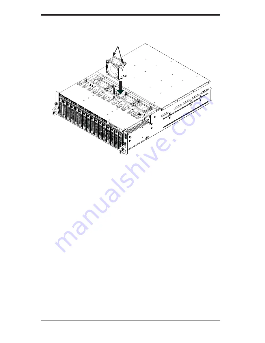
Figure 6-11.  System Fan Placement

Release Tabs

6-9 Power 

Supply

The SC938H chassis includes a redundant 1620 watt power supply, which is auto-
switching capable. This enables it to automatically sense and operate at a 100V to 
240V input voltage. An amber light will be illuminated on the power supply when the 
power is off. An illuminated green light indicates that the power supply is operating.

Power Supply Replacement

In the unlikely event that one of the power supplies needs to be replaced, one power 
supply can be removed without powering-down the system. Replacement power 
supply units may be ordered directly from Supermicro  See the contact information 
in the Preface of this manual or visit www.supermicro.com. 

Содержание 5037MR

Страница 1: ...SUPER SUPERSERVER Super MicrocloudTM 5037MR H8TRF USER S MANUAL Revision 1 0 ...

Страница 2: ...f any such disputes Super Micro s total liability for all claims will not exceed the price paid for the hardware product FCC Statement This equipment has been tested and found to comply with the limits for a Class A digital device pursuant to Part 15 of the FCC Rules These limits are designed to provide reasonable protection against harmful interference when the equipment is operated in a commerci...

Страница 3: ...C938BH R1K62B chassis Chapter 2 Server Installation This chapter describes the steps necessary to install the server into a rack and check out the server configuration prior to powering up the system If your server was ordered without the processor and memory components this chapter will refer you to the appropriate sections of the manual for their installation Chapter 3 System Interface Refer to ...

Страница 4: ...onfiguring the motherboard Chapter 6 Advanced Chassis Setup Refer to Chapter 6 for detailed information on the SC938BH R1K62B 3U server chassis You should follow the procedures given in this chapter when installing removing or reconfiguring drives and when replacing system power supply units and cooling fans Chapter 7 BIOS The BIOS chapter includes an introduction to BIOS and provides detailed inf...

Страница 5: ...v Preface Notes ...

Страница 6: ... Preparing for Setup 2 1 Choosing a Setup Location 2 2 Rack Precautions 2 2 Server Precautions 2 2 Rack Mounting Considerations 2 3 Ambient Operating Temperature 2 3 Reduced Airflow 2 3 Mechanical Loading 2 3 Circuit Overloading 2 3 Reliable Ground 2 3 2 4 Installing the System into a Rack 2 4 Identifying the Sections of the Rack Rails 2 4 Locking Tabs 2 5 Releasing the Inner Rail 2 5 Installing T...

Страница 7: ... 4 3 ESD Precautions 4 3 4 4 Operating Precautions 4 4 Chapter 5 Advanced Motherboard Setup 5 1 Handling the Motherboard 5 1 Precautions 5 1 Unpacking 5 2 5 2 Motherboard Installation 5 2 5 3 Connecting Cables 5 2 5 4 I O Ports 5 2 5 5 Installing the Processor and Heatsink 5 3 Installing an LGA 2011 Processor 5 3 Installing a CPU Heatsink 5 6 5 6 Installing Memory 5 7 How to Install Memory 5 7 Mem...

Страница 8: ...Bracket 6 8 Installing the Backplane onto the Fan Bracket 6 9 Installing the Backplane and Fan Bracket Assembly 6 10 6 6 Removing and Installing Motherboard Nodes 6 11 6 7 Installing an Air Shroud 6 12 6 8 System Fans 6 13 6 9 Power Supply 6 14 Power Supply Replacement 6 14 Chapter 7 BIOS 7 1 Introduction 4 1 Starting BIOS Setup Utility 4 1 How To Change the Configuration Data 4 1 How to Start the...

Страница 9: ...ied for use with the 5037MR H8TRF www supermicro com In addition to the motherboard and chassis various hardware components have been included with the 5037MR H8TRF as listed below Four chassis fans FAN 0133L4 One passive heatsink each node SNK P0047PS One air shroud each node MCP 310 93803 0B One riser card each node RSC RR1U E8 SATA Accessories One SATA backplane BPN SAS 938H Sixteen hot swap ha...

Страница 10: ...p to 128 GB of ECC LV LR R UDIMM DDR3 1600 1333 1066 800 memory This equates to a maximum of 1024 GB for the system Memory modules of the same size and speed should be used See Chapter 5 for details SATA A SATA controller is integrated into the chipset to provide a six port SATA subsystem Two of these are for SATA 3 0 ports SATA0 1 and the rest support SATA 2 0 The SATA drives are hot swappable un...

Страница 11: ...erheat sensors virus protection and BIOS rescue Figure 1 1 Intel C602J Chipset System Block Diagram Note This is a general block diagram See Chapter 5 for details TPM1 2 Header PCH 600MB s SATA III LPC HEALTH INFO LPC I O FLASH SPI 64Mb NCT6776F SPI 2 SATA PORTS BP 2 SATA PORTS BP VGA RTL8201F PHY HERMON WPCM450 WINBOND PCI32 8GT s PCIe x8 SLOT Micro LP PCIe3 0_x8 PCIe3 0_x8 PCIe x8 SLOT 8GT s DDR...

Страница 12: ...iled power supply without shutting down the system Front Control Panel The control panel on the 5037MR H8TRF features a power button LED a power fail LED and eight LEDs to indicate the status of each node in the system Cooling System The SC938BH R1K62B chassis includes four 8 cm fans located behind the back plane Each fan is associated with and controlled by two nodes Each node also has an air shr...

Страница 13: ...uper Micro Computer B V Het Sterrenbeeld 28 5215 ML s Hertogenbosch The Netherlands Tel 31 0 73 6400390 Fax 31 0 73 6416525 Email sales supermicro nl General Information support supermicro nl Technical Support rma supermicro nl Customer Support Asia Pacific Address Super Micro Computer Inc 4F No 232 1 Liancheng Rd Chung Ho Dist New Taipei City 235 Taiwan Tel 886 2 8226 3990 Fax 886 2 8226 3991 Web...

Страница 14: ...1 6 SUPERSERVER 5037MR H8TRF User s Manual Notes ...

Страница 15: ...n and note if it was damaged in any way If the server itself shows damage you should file a damage claim with the carrier who delivered it Decide on a suitable location for the rack unit that will hold the 5037MR H8TRF It should be situated in a clean dust free area that is well ventilated Avoid areas where heat electrical noise and electromagnetic fields are generated You will also need it placed...

Страница 16: ...ttom of the rack are fully extended to the floor with the full weight of the rack resting on them In single rack installation stabilizers should be attached to the rack In multiple rack installations the racks should be coupled together Always make sure the rack is stable before extending a component from it You should extend only one component at a time extending two or more si multaneously may c...

Страница 17: ...Equipment should be mounted into a rack so that the amount of airflow required for safe operation is not compromised Mechanical Loading Equipment should be mounted into a rack so that a hazardous condition does not arise due to uneven mechanical loading Circuit Overloading Consideration should be given to the connection of the equipment to the power supply circuitry and the effect that any possibl...

Страница 18: ... rail will fit a rack between 26 5 and 36 4 deep Identifying the Sections of the Rack Rails The chassis package includes two rail assemblies in the rack mounting kit Each assembly consists of three sections An inner chassis rail that secures directly to the chassis an outer rail that secures to the rack and a middle rail which extends from the outer rail These assemblies are specifically designed ...

Страница 19: ... extended from the rack This prevents the server from coming completely out of the rack when when the chassis is pulled out for servicing Releasing the Inner Rail Releasing Inner Rail from the Outer Rails 1 Identify the left and right outer rail assemblies as described on the previous page 2 Pull the inner rail out of the outer rail until it is fully extended as illustrated below 3 Press the locki...

Страница 20: ...ctly identified 2 Place the inner rail firmly against the side of the chassis aligning the hooks on the side of the chassis with the holes in the inner rail 3 Slide the inner rail forward toward the front of the chassis until the rail clicks into the locked position which secures the inner rail to the chassis 4 Secure the inner rail to the chassis with the screws provided 5 Repeat steps 1 through ...

Страница 21: ...t of the rack If necessary use screws to secure the outer rails to the rack as illustrated above 4 Pull out the rear of the outer rail adjusting the length until it fits within the posts of the rack 5 Hang the hooks of the rear portion of the outer rail onto the slots on the rear of the rack If necessary use screws to secure the rear of the outer rail to the rear of the rack 6 Repeat steps 1 5 for...

Страница 22: ...ocking position of the middle rail 4 Align the chassis inner rails with the front of the middle rails 5 Slide the inner rails on the chassis into the middle rails keeping the pressure even on both sides until the locking tab of the inner rail clicks into the front of the middle rail locking the chassis into the fully extended position 6 Depress the locking tabs of both sides at the same time and p...

Страница 23: ...stall the inner rails on the chassis as previously described on page 2 6 2 Install the whole rail assembly onto the rack as described on page 2 7 3 Release the inner rail without retracting the middle rail 4 Install the chassis onto the middle rail as described in the previous section Note that these figures are for illustrative purposes only Servers should always be installed to racks from the bo...

Страница 24: ...4 Peel off the protective film covering the top cover and the top of the chassis 5 Check that all ventilation openings on the top cover and the top of the chassis are clear and unobstructed Checking the Components and Setup 1 You may have a processor already installed into each of the motherboards Each processor should have its own heatsink attached See Chapter 5 for instructions on processor and ...

Страница 25: ... the Inside of the System Warning Except for short periods of time do NOT operate the server without the cover in place The chassis cover must be in place to allow proper airflow and prevent overheating Remove Three Screws Remove Film From Vents 1 3 1 4 1 2 ...

Страница 26: ... power and data cables have been routed in such a way that they do not block the airflow generated by the fans Keep this in mind when you reroute them after working on the system Providing Power 1 Plug the AC power cords into a high quality power strip that offers protection from electrical noise and power surges 2 It is recommended that you use an uninterruptible power supply UPS 3 Finally depres...

Страница 27: ...in power button on the control panel functions as both an on off switch and as an LED The LED illuminates green when powered on and is not illuminated when powered off A quick press of less than five seconds will sequentially power on all of the nodes in order from one to eight Pressing the button for longer than five seconds will sequentially power down the nodes in order from one to eight Turnin...

Страница 28: ...node status LEDs which indicate the status of each serverboard node Figure 3 1 Node Status LEDs LED Appearance Description Solid Green The node is powered on and operating normally Blinking Green The node is in the process of shutting down Solid Red The node is detecting an overheated condition 1Hz Blinking Red The node is detecting a fan failure 25Hz Blinking Red The node is detecting a power fai...

Страница 29: ... illuminated this LED indicates drive activity A connection to the SATA backplane enables this LED to blink on and off when that particular drive is being accessed Red Indicates a drive failure If one of the drives fail you should also be notified by your system management software Hard Drive Carrier LEDs Figure 3 2 Hard Drive Carrier LEDs 3 5 Node LEDs Individual LEDS are located on the back of e...

Страница 30: ...n the node is powered off UIO Button and LED This button is used to identify the node within the system It is illuminated blue when activated it is off when inactive Failure LED This LED is illuminated red when a failure has occurred and off during normal opera tion If illuminated check that the two corresponding hard drives are fully inserted into their bays with their handles completely pushed i...

Страница 31: ... power you should first power down the system with the operating system first and then unplug the power cords of all the power supply units in the system When working around exposed electrical circuits another person who is familiar with the power off controls should be nearby to switch off the power if neces sary Use only one hand when working with powered on electrical equipment This is to avoid...

Страница 32: ...ects from your body which are excellent metal conductors that can create short circuits and harm you if they come into contact with printed circuit boards or areas where power is present Motherboard Battery CAUTION There is a danger of explosion if the onboard battery is installed upside down which will reverse its polarites see Figure 4 1 This battery must be replaced only with the same or an equ...

Страница 33: ... use Touch a grounded metal object before removing the board from the antistatic bag Do not let components or PCBs come into contact with your clothing which may retain a charge even if you are wearing a wrist strap Handle a board by its edges only do not touch its components peripheral chips memory modules or contacts When handling chips or modules avoid touching their pins Put the motherboard an...

Страница 34: ...his practice is not strictly followed Figure 4 1 Installing the Onboard Battery TH UM TTER TTER HO ER Please handle used batteries carefully Do not damage the battery in any way a damaged battery may release hazardous materials into the environment Do not discard a used battery in the garbage or a public landfill Please comply with the regulations set up by your local hazardous waste management ag...

Страница 35: ...ly see previous chapter To prevent the motherboard from bending keep one hand under the center of the board to support it when handling The following measures are generally sufficient to protect your equipment from electric static discharge Precautions Use a grounded wrist strap designed to prevent Electrostatic Discharge ESD Touch a grounded metal object before removing any board from its antista...

Страница 36: ... be shipped assebled in its carrier and not by itself See Chapter 6 for instructions on installing and removing the motherboard nodes from the chassis 5 3 Connecting Cables The 5037MR H8TRF server was designed as a cableless system As a result all power and data connections to the motherboard nodes are made whenever a node is installed into its bay in the chassis This covers the main power connect...

Страница 37: ...nly Make sure to install the motherboard into the chassis before you install the CPU heatsinks When receiving a motherboard without a processor pre installed make sure that the plastic CPU socket cap is in place and none of the socket pins are bent otherwise contact your retailer immediately Refer to the Supermicro web site for updates on CPU support Installing an LGA 2011 Processor Follow the pro...

Страница 38: ... WARNING plastic cap from the socket 5 Use your thumb and index finger to hold the CPU by its edges Align the CPU keys which are semi circle cutouts against the socket keys 6 Once they are aligned carefully lower the CPU straight down into the socket Do not drop the CPU on the socket Do not move the CPU horizontally or vertically and do not rub the CPU against any pins of the socket which may dama...

Страница 39: ...again and double check that the CPU is aligned properly 7 With the CPU in the socket inspect the four corners of the CPU to make sure that they are flush with the socket 8 Close the load plate Lock the lever labeled Close 1st then lock the lever labeled Open 1st Use your thumb to gently push the load levers down until the lever locks OPEN1st OPEN1st OPEN1st OPEN1st Lever Lock Push down and lock th...

Страница 40: ...y damage the CPU 5 Add the two remaining screws then finish the installation by fully tightening all four screws Installing a CPU Heatsink Removing the Heatsink 1 Unscrew and remove the heatsink screws from the motherboard in the sequence as show in the picture above 2 Hold the heatsink and gently wriggle the heatsink to loosen it from the CPU Do not use excessive force when wriggling the heatsink...

Страница 41: ...n our web site for possible updates to memory support 1 2 7 8 DESIGNED IN USA X9SRD F BAR CODE 1 1 2 2 1 2 1 B 1 1 3 1 1 3 1 3 1 1 3 1 3 1 1 1 3 A C A C A C 48 28 REV 1 01 CLOSE 1st OPEN 1st U43 SW1 JUIDB1 T SGPIO2 J67 P1 DIMMC1 P1 DIMMD1 P1 DIMMA1 P1 DIMMB1 JTPM1 JPCIE1 JUSB2 CPU1 BT1 JIPT2 IPMI_LAN JKVM1 J66 JI2C1 JI2C2 J93 JSD1 FAN1 JPCIE2 JPME1 JPB1 JPG1 JWD1 JPEW1 JWP1 JVR1 JPME2 LED6 LED4 LE...

Страница 42: ...stalling and Removing DIMMs Position the DIMM module s bottom key so that it aligns with the receptive point on the slot When the module is prop erlly inserted the lock re lease tabs will automatically secure the DIMM module locking it into place Push a lock release tab to the release position Make sure that the side notches of the DIMM module aligns with the lock release tab of the slot as it is ...

Страница 43: ...riser card may be removed from the motherboard by removing the riser card screw Memory Population Guidelines When installing memory modules the DIMM slots should be populated in the fol lowing order DIMMA1 DIMMB1 DIMMC1 and DIMMD1 Always use DDR3 DIMM modules of the same size type and speed Mixed DIMM speeds can be installed However all DIMMs will run at the speed of the slowest DIMM The motherboa...

Страница 44: ...node and motherboard may vary from those illustrated 6 Slide the expansion cards bracket into the PCI card slot and fit it with the opening in the rear of the node 7 Close the PCI card slot clip to secure the expansion card Note The PCI slot shields protect the motherboard and its components from EMI and aid in proper ventilation so make sure there is always a shield covering each unused slot ...

Страница 45: ... LED6 LED4 LED5 1 2 NORMAL 2 3 ME RECOVERY 3 GND 2 DATA 1 CLK JVR1 Watch Dog JWP1 Write Protect JPEW1 PCIE2 SLOT 1 2 MAIN POWER 2 3 STBY POWER JPB1 BMC 1 2 ENABLE 2 3 DISABLE VGA 1 2 ENABLE 2 3 DISABLE JPG1 JWD1 2 3 NMI 1 2 RST SATA DOM POWER I SATA5 JPME1 JTPM1 TPM PORT80 OFF DISABLE JI2C2 ON ENABLE JI2C1 JPME2 1 2 NORMAL 2 3 ME MANUFACTURING MODE USB2 3 MICRO LP PCI E 3 0 X8 I SATA4 JSD1 UID SLO...

Страница 46: ...5 11 JI2C1 JI2C2 SMB to PCI Slots See Section 5 11 X9SRD F Quick Reference MICRO LP SLOT PCI E Micro LP Slot SPKR1 Internal Speaker Buzzer JTPM1 Trusted Platform Module TPM Header JUSB2 USB Header USB 2 3 I SATA4 I SATA5 Internal SATA Ports JSD1 SATA Disk On Module DOM Power Connector T SGPIO2 Serial Link General Purpose Header DIMMA1 DIMMD1 DIMM Memory Slots IF PWR Back Panel Edge Connector SATA ...

Страница 47: ...to the backplane of the server chassis Through this connector the motherboard will receive its power and com municate with the rest of the system hard drives warning lamps etc Universal Serial Bus USB Two Universal Serial Bus ports USB 2 3 are located on the on the moth erboard These are available on a header There are also two ports USB 0 1 available through the KVM port Cables are not included S...

Страница 48: ...ED is located right next to the IPMI port Push this button to turn on the motherboard When lit it indicates that this particular motherboard is turned on UID Button The Unit ID UID Button is used in conjunction with the UID switch in front of the chassis and the UID LED located next to it When the switch is turned on the UID LED will turn on making pinpointing of the node from the front or back pa...

Страница 49: ...s either on only one pin or completely removed Connector Pins Jumper Setting 3 2 1 3 2 1 CMOS Clear JBT1 is used to clear CMOS which will also clear any passwords Instead of pins this jumper consists of contact pads to prevent accidentally clearing the contents of CMOS To clear CMOS 1 First power down the system and unplug the power cord s It is also recom mended that you remove the onboard batter...

Страница 50: ...tem when a software application hangs Close pins 1 2 to reset the system if an applica tion hangs Close pins 2 3 to generate a non maskable interrupt signal for the application that hangs See the table on the right for jumper settings Watch Dog must also be enabled in the BIOS SMB I2 C Bus to PCI Slots JI2C1 JI2C2 Jumpers JI2 C1 and JI2 C2 allow you to connect the System Management Bus SMB to the ...

Страница 51: ... activated when this feature is enabled BIOS Recovery Jumper Settings Pin Definition 1 2 Enabled 2 3 Disabled Default BIOS Write Protect JPWP1 When enabled The firmware is pro tected from being accidentally erased or modified BIOS Write Protect Jumper Settings Pin Definition 1 2 Enabled Default 2 3 Disabled PCI E Vaux Select JPEW1 This jumper is used to select whether the PCI E 3 3Vaux is from the...

Страница 52: ...dicator Blinking IPMI is ready for use System Fan Fail LED LED5 indicates a system or fan failure when illuminated Please see the table on the right for message descriptions System Fan Fail LED Indicator LED Color Definition Off System Normal Red Solid System Overheat Red Blinking Fan Failure Red Blinking Power Failure Unit ID LED The Unit LED LED6 is controlled by the Unit ID Button It enables th...

Страница 53: ...nd then the drivers The necessary drivers are all included on the Supermicro CDs that came packaged with your motherboard Driver Tool Installation Display Screen Note Click the icons showing a hand writing on paper to view the readme files for each item Click the computer icons to the right of these items to install each item from top to the bottom one at a time After installing each item you must...

Страница 54: ...ucial system information such as CPU temperature system voltages and fan status See the Figure below for a display of the Supero Doctor III interface Note The default User Name and Password for SuperDoctor III is ADMIN AD MIN Note When SuperDoctor III is first installed it adopts the temperature threshold settings that have been set in BIOS Any subsequent changes to these thresholds must be made w...

Страница 55: ...aded from our Web Site at ftp ftp supermicro com utility Supero_Doctor_III You can also download the SDIII User s Guide at http www supermicro com PRODUCT Manuals SDIII UserGuide pdf For Linux we will recommend using Supero Doctor II Supero Doctor III Interface Display Screen Remote Control ...

Страница 56: ...5 22 SUPERSERVER 5037MR H8TRF User s Manual Notes ...

Страница 57: ...d circuit boards PCBs it is important to handle them very carefully The following measures are generally sufficient to protect your equipment from ESD damage Precautions Use a grounded wrist strap designed to prevent static discharge Touch a grounded metal object before removing any board from its antistatic bag Handle a board by its edges only do not touch its components peripheral chips memory m...

Страница 58: ...ce 2 Remove the three screws which secure the top cover to the chassis as il lustrated above 3 Lift the top cover up and off the chassis 4 Peel off the protective film covering the top cover and the top of the chassis 5 Check that all ventilation openings on the top cover and the top of the chassis are clear and unobstructed Warning Except for short periods of time do NOT operate the server withou...

Страница 59: ...des Each node controls two hard drives and shares a fan with the node beside it Note that if a node is pulled out of the chassis the hard drives associated with that node will power down 1 A 1 B 1 E 1 G 1 F 1 H 1 C 1 D Corresponding Nodes Fans and HDDs Node Fan HDDs Node 1 Fan 1 HDDs A1 and A2 Node 2 Fan 1 HDDs B1 and B2 Node 3 Fan 2 HDDs C1 and C2 Node 4 Fan 2 HDDs D1 and D2 Node 5 Fan 3 HDDs E1 ...

Страница 60: ...res sixteen hot swappable hard drives These hard drives are contained in drive carriers and may be removed without powering down the system Removing Hard Drive Carriers from the Chassis 1 Press the release button on the drive carrier which will extend the drive car rier handle 2 Use the drive carrier handle to pull the drive out of the chassis ...

Страница 61: ... Carrier 1 Remove the hard drive carrier from the chassis as described in the previous section and lay the drive carrier on a flat surface 2 Remove the two screws securing the dummy drive to the drive carrier 3 Lift the dummy drive from the drive carrier Warning Except for short periods of time while swapping hard drives do not operate the server with the hard drive bays empty All carriers even wi...

Страница 62: ...Hard Drive into the Drive Carrier 1 Place the hard drive carrier on a flat surface 2 Insert the hard drive into the carrier with the printed circuit board side facing downward and so that the mounting holes in the drive align with those in the drive carrier 3 Secure the hard drive to the carrier with the four screws included with the hard drive 4 Use the open handle of the drive carrier to insert ...

Страница 63: ...e follow the instructions below to replace it Removing the Backplane and Fan Bracket Assembly Removing the Backplane and Fan Bracket from the Chassis 1 Power down the system and disconnect it from any power source 2 Remove the chassis cover as described in section 6 2 of this manual 3 Disconnect all cabling to the backplane 4 Remove the six screws securing the fan bracket to the chassis and set th...

Страница 64: ... brackets to the sides of the fan bracket and set them aside for later use Remove the side mounting brackets 2 Remove the eleven screws securing the backplane to the fan bracket and set these screws aside for later use 3 Hold the backplane by its edges and carefully remove it from the fan bracket 1 2 Figure 6 7 Removing the Backplane from the Fan Bracket 1 1 1 1 1 3 ...

Страница 65: ...sis 2 Hold the backplane by its edges and carefully place it against the fan mount ing bracket aligning the mounting holes in the backplane with those in the fan bracket 3 Secure the two side mounting brackets to the backplane with the eight screws previously set aside 4 Secure the backplane to the front of the fan bracket using the eleven screws previously set aside 5 Reconnect all wiring to the ...

Страница 66: ...ckplane and Fan Bracket 1 Ensure that the chassis has been disconnected from any power source 2 Remove the chassis cover as described in Section 6 2 3 Reconnect the wiring to the backplane 4 Insert the fan bracket and backplane assembly into the chassis as illustrated above 5 Secure the fan bracket to the chassis with the six screws that were previously set aside ...

Страница 67: ...drives See the table in Section 6 3 to determine which hard drives are controlled by each node Removing Nodes from the System 1 Power down the individual node by pressing that node s power button 2 Press and hold down the release tab on the back of the node 3 Using the node s handle pull the node from the chassis Warning Except for short periods of time while swapping nodes do not operate the serv...

Страница 68: ...re that the motherboard expansion card if present and all compo nents are properly installed in each motherboard node 2 Place the air shroud over the motherboard as shown below The air shroud sits behind the system fans and goes over the top of the motherboard and its components Secure by inserting screws through the tabs and tightening 3 Repeat the procedure for the remaining nodes 4 Reverse this...

Страница 69: ...m is operating to determine which fan has failed Never run the server for an extended period of time with the top cover open 2 Remove the failed fan s power cord from the backplane 3 Simultaneously squeeze both release tabs on the top of the fan module 4 Lift the fan module up and out of the chassis 5 Place the replacement fan into the vacant space in the fan bracket while mak ing sure the arrows ...

Страница 70: ... voltage An amber light will be illuminated on the power supply when the power is off An illuminated green light indicates that the power supply is operating Power Supply Replacement In the unlikely event that one of the power supplies needs to be replaced one power supply can be removed without powering down the system Replacement power supply units may be ordered directly from Supermicro See the...

Страница 71: ...at the top of the power supply 3 Push and hold the release tab on the back of the power supply 4 Pull the power supply out using the handle provided 5 Push the replacement power supply module into the chassis power bay until it clicks into the locked position 6 Plug the AC power cord back into the power supply module and power up the nodes if needed with a single power supply failure the nodes sho...

Страница 72: ...6 16 SUPERSERVER 5037MR H8TRF User s Manual Notes ...

Страница 73: ...l the options that can be configured Grayed out options cannot be configured Options in blue can be configured by the user The right frame displays the key legend Above the key legend is an area reserved for a text message When an option is selected in the left frame it is highlighted in white Often informational text will accompany it Note the AMI BIOS has default informational text built in Supe...

Страница 74: ...Do not upgrade the BIOS unless your system has a BIOS related issue Flashing the wrong BIOS can cause irreparable damage to the system In no event shall Supermicro be liable for direct indirect special incidental or consequential damages arising from a BIOS update If you have to update the BIOS do not shut down or reset the system while the BIOS is updating This is to avoid possible boot failure 7...

Страница 75: ...he Tab key or the arrow keys to move between fields The date must be entered in Day MM DD YY format The time is entered in HH MM SS format Note The time is in the 24 hour format For example 5 30 P M appears as 17 30 00 Supermicro X9SRD F Version This item displays the version of the BIOS used in the system Build Date This item displays the day this version of BIOS was built Memory Information Tota...

Страница 76: ...isabled to display the POST messages Select Enabled to display the OEM logo instead of the normal POST messages The op tions are Enabled and Disabled AddOn ROM Display Mode This sets the display mode for Option ROM The options are Force BIOS and Keep Current Bootup Num Lock This feature selects the Power on state for Numlock key The options are Off and On Wait For F1 If Error This forces the syste...

Страница 77: ...ant Off if you want the system to instantly power off when the Power Button is pressed The options are 4 Seconds Override and Instant Off Restore on AC Power Loss Use this feature to set the power state after a power outage Select Power Off for the system power to remain off after a power loss Select Power On for the system power to be turned on after a power loss Select Last State to allow the sy...

Страница 78: ...elm the processor or damage the system during an attack The default is Enabled Refer to Intel and Microsoft Web Sites for more information Intel AES NI Set to Enabled to use the processor s Advanced Encryption Standard AES feature The options are Enabled and Disabled MLC Streamer Prefetcher Available when supported by the CPU If set to Enabled the MLC mid level cache streamer prefetcher will prefe...

Страница 79: ...Step Technology allows the system to automati cally adjust processor voltage and core frequency in an effort to reduce power consumption and heat dissipation Please refer to Intel s web site for detailed information The options are Disabled and Enabled Turbo Mode This feature allows processor cores to run faster than marked frequency in specific conditions The options are Disabled and Enabled CPU ...

Страница 80: ...onds where the Long Dura tion Power Limit is maintained Short duration power limit During Turbo Mode the system may exceed the processor s default power setting and exceed the Short Duration Power limit By increasing this value the processor can provide better performance for a short duration XChipset Configuration WARNING Setting the wrong values in the following sections may cause the system to ...

Страница 81: ...link speed for this slot The options are GEN1 GEN2 and GEN3 Port 1A Link Speed This feature enables the user to select the target link speed for this slot The options are GEN1 GEN2 and GEN3 Port 1A Link Speed This feature enables the user to select the target link speed for this slot The options are GEN1 GEN2 and GEN3 Port 1A Link Speed This feature enables the user to select the target link speed...

Страница 82: ...tions are Auto 1 Way 2 Way 4 Way and 8 Way Patrol Scrub Patrol Scrubbing is a process that allows the CPU to correct correctable memory errors detected on a memory module and send the correction to the requestor the original source When this item is set to Enabled the North Bridge will read and write back one cache line every 16K cycles if there is no delay caused by internal processing By using t...

Страница 83: ...d Host Controller Interface EHCI The options are Enabled and Disabled Legacy USB Support This feature enables support for legacy USB devices Select Auto to disable legacy support if USB devices are not present Select Disabled to have USB devices available only for EFI applications The options are Enabled Disabled and Auto Port 60 64 Emulation This feature enables I O port 60h 64h emulation support...

Страница 84: ...e SATA controller and sets the compatibility mode The options are Disabled Enhanced and Compat ible The default of Serial ATA Controller 0 is Compatible The default of Serial ATA Controller 1 is Enhanced AHCI Mode The following items are displayed when AHCI Mode is selected Aggressive Link Power Management When Enabled the SATA AHCI controller manages the power usage of the SATA link The controlle...

Страница 85: ...t the PCI PnP configurations for the following items PCI ROM Priority In case of multiple Option ROMs Legacy and EFI compatible this feature speci fies what ROM to launch The options are Legacy ROM and EFI Compatible ROM PCI Latency Timer This feature sets the latency Timer of each PCI device installed on a PCI bus Se lect 64 to set the PCI latency to 64 PCI clock cycles The options are 32 PCI Bus...

Страница 86: ...and Force L0s Onboard LAN Option ROM Select This feature selects whether to load the iSCSI or PXE onboard LAN option ROM The options are iSCSI and PXE Load Onboard LAN1 Option ROM Load Onboard LAN2 Option ROM This feature is to enable or disable the onboard option ROMs The default for LAN 1 is Enabled The default for LAN 2 is Disabled Load Onboard SAS Option ROM Select Enabled to use the onboard S...

Страница 87: ...ction Settings This feature allows the user to specify how the host computer will exchange data with the client computer which is the remote computer used by the user Terminal Type This feature allows the user to select the target terminal emulation type for Con sole Redirection Select VT100 to use the ASCII character set Select VT100 to add color and function key support Select ANSI to use the ex...

Страница 88: ... data communication Select 2 Stop Bits if slower devices are used The options are 1 and 2 Flow Control This feature allows the user to set the flow control for Console Redirection to prevent data loss caused by buffer overflow Send a Stop signal to stop send ing data when the receiving buffer is full Send a Start signal to start sending data when the receiving buffer is empty The options are None ...

Страница 89: ... the user to select the target terminal emulation type for Con sole Redirection Select VT100 to use the ASCII character set Select VT100 to add color and function key support Select ANSI to use the extended ASCII character set Select VT UTF8 to use UTF8 encoding to map Unicode characters into one or more bytes The options are ANSI VT100 VT100 and VT UTF8 Bits Per Second This item sets the transmis...

Страница 90: ... mode The options are Suspend Disabled S1 CPU Stop Clock High Precision Event Timers Select Enabled to activate the High Performance Event Timer HPET that produces periodic interrupts at a much higher frequency than a Real time Clock RTC does in synchronizing multimedia streams providing smooth playback and reducing the de pendency on other timestamp calculation devices such as an x86 RDTSC Instru...

Страница 91: ... Runtime Error Logging Support Change this item to enable or disable runtime error logging The options are En abled and Disabled Memory Correction Error Threshold Change this item to define the system s memory correction error threshold Directly enter a numeric value The default value is 10 PCI Error Logging Support Change this item to enable or disable runtime error logging The options are En abl...

Страница 92: ...System Boot Event logging to enabled or disabled The options are Disabled and Enabled MECI The Multiple Event Count Increment MECI counter counts the number of times a duplicate event must happen before the MECI counter is incremented This is a numeric value The default value is 1 METW The Multiple Event Time Window METW defines number of minutes must pass between duplicate log events before MECI ...

Страница 93: ...SEL Components Change this item to enable or disable all features of System Event Logging The options are Enabled and Disabled When Enabled the fol lowing can be configured Erase SEL This option erases all logged SEL events The options are No Yes On Next reset and Yes On Every reset When SEL Full This option automatically clears the System Event Log memory of all messages when it is full The optio...

Страница 94: ...ser Static When Dynamic is selected all the options below are automatically assigned to the sys tem by itself or by an external DHCP server If Static is selected the IP Address Subnet Mask and Gateway Address must be manually entered below The options are Static and DHCP Station IP Address Enter the IP address for this machine This should be in decimal and in dotted quad form i e 192 168 10 253 Th...

Страница 95: ...f priority from which the systems boots during startup Boot Option 1 Boot option 2 etc The settings are any detected boot device and Disabled USB Device BBS Priorities This option sets the order of the legacy USB devices detected by the motherboard Add New Boot Option This feature allows the user to add a new boot device Add Boot Option Use this item to enter the name of the new boot option ...

Страница 96: ...ion Use this item to enter the boot option path using the following format fs0 path filename efi Create Use this item to create the new boot option based on the settings above XDelete Boot Option This feature allows the user to delete a previously defined boot device from the boot priorities list The settings are any pre defined boot device ...

Страница 97: ...ed ONLY this password will need to be entered during each system startup or boot and will also have Administrator rights in the setup Passwords must be at least 3 and up to 20 characters long Administrator Password Press Enter to create a new or change an existing Administrator password User Password Press Enter to create a new or change an existing User password ...

Страница 98: ...uter Select Discard Changes and Exit from the Exit menu and press Enter Save Changes and Reset When you have completed the system configuration changes select this option to leave the BIOS Setup Utility and reboot the computer so the new system con figuration parameters can take effect Select Save Changes and Exit from the Exit menu and press Enter Save Changes When you have completed the system c...

Страница 99: ...faults To set this feature select Save as User Defaults from the Exit menu and press En ter This enables the user to save any changes to the BIOS setup for future use Restore User Defaults To set this feature select Restore User Defaults from the Exit menu and press En ter Use this feature to retrieve user defined settings that were saved previously Boot Override Listed on this section are other b...

Страница 100: ...4 28 SUPERSERVER 5037MR H8TRF User s Manual Notes ...

Страница 101: ... Beep Codes for recoverable POST errors Recoverable POST Error Beep Codes When a recoverable type of error occurs during POST BIOS will display a POST code that describes the problem BIOS may also issue one of the following beep codes 1 long and two short beeps video configuration error 1 repetitive long beep no memory detected 1 continuous beep with the front panel Overheat LED on system overheat...

Страница 102: ...A 2 SUPERSERVER 5037MR H8TRF User s Manual Notes ...

Страница 103: ...ch node supports up to 128 GB of ECC DDR3 1600 1333 1066 RDIMM memory Note See the memory section in Chapter 5 for details Drive Bays Sixteen hot swap drive bays to house 3 5 SATA drives Expansion Slots Each node supports the use of one PCI E 3 0 x8 low profile add on card 6 6 maximum length Motherboard X9SRD F proprietary form factor Dimensions 4 75 x 15 95 120 7 x 405 mm Chassis SC938BH R1K62B 3...

Страница 104: ...ive Humidity 20 to 95 non condensing Non operating Relative Humidity 5 to 95 non condensing Regulatory Compliance Electromagnetic Emissions FCC Class A EN 55022 Class A EN 61000 3 2 3 3 CISPR 22 Class A Electromagnetic Immunity EN 55024 CISPR 24 EN 61000 4 2 EN 61000 4 3 EN 61000 4 4 EN 61000 4 5 EN 61000 4 6 EN 61000 4 8 EN 61000 4 11 Safety EN 60950 IEC 60950 Compliant UL Listed USA CUL Listed C...

Страница 105: ...B 3 Appendix B System Specifications ...

Страница 106: ...perform be reasonably expected to result in significant injury or loss of life or catastrophic property damage Accordingly Supermicro dis claims any and all liability and should buyer use or sell such products for use in such ultra hazardous applications it does so entirely at its own risk Furthermore buyer agrees to fully indemnify defend and hold Supermicro harmless for and against any and all c...

Отзывы: