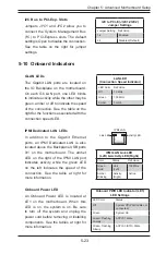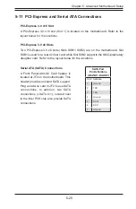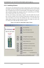
5-20
SUPERSERVER 2027TR-H70RF/H70FRF/H70QRF USER'S MANUAL
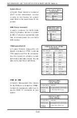
System Reset
A System Reset header is located at
JRST1 on the motherboard. Connect
a cable to this header for system
reset. Refer to the layout below for the
location.
System Reset (JRST1)
Pin Defi nition
Pin Setting Defi nition
Pin 1
Signal
Pin 2
Ground
DOM Power Connector
A power connector for SATA DOM
(Disk_On_Module) devices is located
at JSD1. Connect an appropriate cable
here to provide power for your SATA
DOM devices.
DOM PWR (JSD1)
Pin Defi nitions
Pin# Defi nition
1
+5V
2
Ground
3
Ground
TPM Header/Port 80
A Trusted Platform Module/Port 80
header is located at JTPM1 to provide
TPM support and Port 80 connection.
Use this header to enhance system
performance and data security. See the
table on the right for pin defi nitions.
TPM/Port 80 Header (JTPM1)
Pin Defi nitions
Pin# Defi nition
Pin# Defi nition
1
LCLK
2
GND
3
LFRAME#
4
<(KEY)>
5
LRESET#
6
+5V (X)
7
LAD 3
8
LAD 2
9
+3.3V
10
LAD1
11
LAD0
12
GND
13
SMB_CLK4
14
SMB_DAT4
15
+3V_DUAL
16
SERIRQ
17
GND
18
CLKRUN# (X)
19
LPCPD#
20
LDRQ# (X)
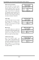
JTAG Scan (JPP0)
Jumper Settings
Jumper Setting Defi nition
Pins 1/2, 3/4
Including CPU2 in JTAG Scan
Pins 2/3
(Default)
JTAG Scan: CPU1 only
JTAG Scan (JPP1)
Jumper Settings
Jumper Setting Defi nition
Pins 1/2, 3/4
including CPU1 in JTAG Scan
Pins 2/3
(Default)
JTAG Scan: CPU2 only
IPMB I2C SMB
A System Management Bus header
for the IPMI slot is located at JIPMB1.
Connect an appropriate cable here to
use the IPMB I
2
C connection on your
system.
Содержание 2027TR-H70FRF
Страница 1: ...SUPERSERVER 2027TR H70QRF 2027TR H70FRF 2027TR H70RF SUPER USER S MANUAL Revision 1 0 ...
Страница 5: ...v SUPERSERVER 2027TR H70RF H70FRF H70QRF USER S MANUAL Notes ...
Страница 10: ...x Notes SUPERSERVER 2027TR H70RF H70FRF H70QRF USER S MANUAL ...
Страница 30: ...2 12 SUPERSERVER 2027TR H70RF H70FRF H70QRF USER S MANUAL Notes ...
Страница 34: ...SUPERSERVER 2027TR H70RF H70FRF H70QRF USER S MANUAL 3 4 Notes ...
Страница 68: ...5 30 SUPERSERVER 2027TR H70RF H70FRF H70QRF USER S MANUAL Notes ...
Страница 75: ...Chapter 6 Advanced Chassis Setup 6 7 Figure 6 5 Replacing a System Fan in the Fan Housing ...
Страница 81: ...Chapter 6 Advanced Chassis Setup 6 13 Figure 6 12 Installing the Motherboard in the Motherboard Node Drawer ...
Страница 116: ...A 2 SUPERSERVER 2027TR H70RF H70FRF H70QRF USER S MANUAL Notes ...
Страница 119: ...B 3 Appendix B System Specifications Notes ...

