Chapter 5: Advanced Motherboard Setup
5-3
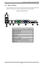
5-3 Rear I/O Ports
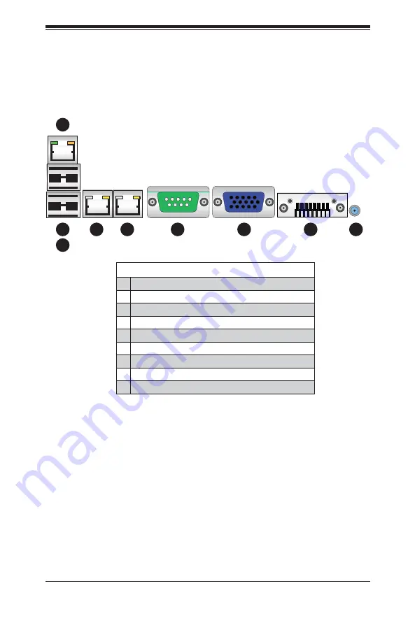
The rear I/O ports are color coded in conformance with the PC 99 specifi cation. See
Figure 5-1 below for the colors and locations of the various I/O ports.
Figure 5-1. Rear I/O Ports
Back Panel I/O Port Locations and Defi nitions
1.
Back Panel USB Port 0
2.
Back Panel USB Port 1
3.
IPMI_Dedicated LAN
4.
Gigabit LAN 1
5.
Gigabit LAN 2
6.
COM Port 1 (Turquoise)
7.
Back Panel VGA (Blue)
8.
Infi niBand Connector (For X9DRT-HIBQF/HIBFF)
9.
UID Switch
2
1
5
3
4
6
7
9
8
Содержание 2027TR-H70FRF
Страница 1: ...SUPERSERVER 2027TR H70QRF 2027TR H70FRF 2027TR H70RF SUPER USER S MANUAL Revision 1 0 ...
Страница 5: ...v SUPERSERVER 2027TR H70RF H70FRF H70QRF USER S MANUAL Notes ...
Страница 10: ...x Notes SUPERSERVER 2027TR H70RF H70FRF H70QRF USER S MANUAL ...
Страница 30: ...2 12 SUPERSERVER 2027TR H70RF H70FRF H70QRF USER S MANUAL Notes ...
Страница 34: ...SUPERSERVER 2027TR H70RF H70FRF H70QRF USER S MANUAL 3 4 Notes ...
Страница 68: ...5 30 SUPERSERVER 2027TR H70RF H70FRF H70QRF USER S MANUAL Notes ...
Страница 75: ...Chapter 6 Advanced Chassis Setup 6 7 Figure 6 5 Replacing a System Fan in the Fan Housing ...
Страница 81: ...Chapter 6 Advanced Chassis Setup 6 13 Figure 6 12 Installing the Motherboard in the Motherboard Node Drawer ...
Страница 116: ...A 2 SUPERSERVER 2027TR H70RF H70FRF H70QRF USER S MANUAL Notes ...
Страница 119: ...B 3 Appendix B System Specifications Notes ...

