background image

16

SuperStorage Server 6048-E1CR90L User's Manual

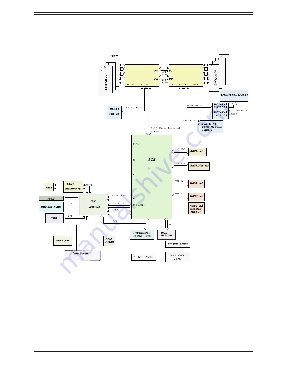
Figure 1-6. Intel PCH C612 Chipset: System Block Diagram

Note:

 This is a general block diagram and may not exactly represent the features on your 

motherboard. See the System Specifications appendix for the actual specifications of your 

motherboard.

Processor 2

DDR4

Processor 1

DDR4

DDR4

DDR4

System Block Diagram

Содержание SuperStorage Server 6048R-E1CR90L

Страница 1: ...USER S MANUAL Revision 1 0 6048R E1CR90L SuperStorage Server...

Страница 2: ...operated in a commercial environment This equipment generates uses and can radiate radio frequency energy and if not installed and used in accordance with the manufacturer s instruction manual may cau...

Страница 3: ...com Notes For your system to work properly please follow the links below to download all necessary drivers utilities and the user s manual for your server Supermicro product manuals http www supermicr...

Страница 4: ...lation in a Rack 2 1 Preparing for Setup 17 Choosing a Setup Location 17 Rack Precautions 17 Server Precautions 18 Rack Mounting Considerations 18 Ambient Operating Temperature 18 Airflow 18 Mechanica...

Страница 5: ...ure 40 Motherboard Battery 41 3 4 Chassis Components 42 Storage Drives 42 Drive Carrier Indicators 42 Controller to Drive Configuration 43 Adding or Replacing Hard Drives 44 Two Hard Disk Drives at th...

Страница 6: ...ystem 68 5 2 Driver Installation 69 5 3 SuperDoctor 5 70 Chapter 6 BIOS 6 1 Introduction 71 Starting BIOS Setup Utility 71 6 2 Main Setup 71 6 3 Advanced Setup Configurations 73 6 4 Event Logs 100 6 5...

Страница 7: ...ddress Super Micro Computer B V Het Sterrenbeeld 28 5215 ML s Hertogenbosch The Netherlands Tel 31 0 73 6400390 Fax 31 0 73 6416525 Email sales supermicro nl General Information support supermicro nl...

Страница 8: ...Casandra virtual storage environments single instance storage and data deduplication In addition to the motherboard and chassis several included parts are listed below Main Parts List Description Part...

Страница 9: ...LRDIMM memory 512 GB of ECC LRDIMM memory 256 GB of ECC RDIMM memory Type 2400 2133 1866 1600 1333MHz ECC DDR4 SDRAM 72 bit DIMM sizes LRDIMM 64GB 32GB RDIMM 32GB 16GB 8GB 4GB Chipset Intel PCH C612 D...

Страница 10: ...he uinit identification UID button turns on or off the blue light function of the Information LED and a blue LED on the rear of the chassis These are used to locate the server in large racks and serve...

Страница 11: ...1Hz Fan failure check for an inoperative fan Blinking red 0 25Hz Power failure check for a non operational power supply Solid blue Local UID has been activated Use this function to locate the server i...

Страница 12: ...E1CR90L User s Manual Chassis Rear The illustration below shows the features included on the rear of the chassis Power supply modules display status lights Figure 1 3 Rear View Power Supplies I O Port...

Страница 13: ...13 Chapter 1 Introduction Chassis Top Figure 1 4 Top View 90 Drives Mounted Vertically...

Страница 14: ..._LAN COM2 VGA I SATA3 I SATA2 I SATA0 I SATA1 TPM PORT80 P2 DIMMG1 LE2 P2 DIMME1 P2 DIMMF1 P1 DIMMC1 P1 DIMMD1 P1 DIMMB1 P1 DIMMA1 Battery BIOS JPS1 P2 DIMMH1 Intel PCH AST2400 BMC Avago SAS3008 Avago...

Страница 15: ...0 3 supported by Intel PCH I SATA1 I SATA 3 support SMCI SuperDOM connections w power pins built in SFP LAN1 SFP LAN4 JX1_SFP1 10G SFP small form factor pluggable Networking LAN ports 1 4 SW1 UID UID...

Страница 16: ...pset System Block Diagram Note This is a general block diagram and may not exactly represent the features on your motherboard See the System Specifications appendix for the actual specifications of yo...

Страница 17: ...is product should be installed only in a Restricted Access Location dedicated equipment rooms service closets etc This product is not suitable for use with visual display workplace devices acccording...

Страница 18: ...g Temperature If installed in a closed or multi unit rack assembly the ambient operating temperature of the rack environment may be greater than the room s ambient temperature Therefore consideration...

Страница 19: ...stem remains stable The following guidelines are provided to ensure your safety This unit should be mounted at the bottom of the rack if it is the only unit in the rack When mounting this unit in a pa...

Страница 20: ...ail that secures to the rack and a middle rail which extends from the outer rail These assemblies are specifically designed for the left and right side of the chassis looking from the front and so lab...

Страница 21: ...the server from coming completely out of the rack when when the chassis is pulled out for servicing 1 Pull the inner rail out of the outer rail until it is fully extended 2 Pull the thin plastic locki...

Страница 22: ...aligning the mushroom pins on the side of the chassis with the holes in the inner rail 3 Slide the inner rail forward toward the front of the chassis and under the mushroom pins until the quick relea...

Страница 23: ...post of the rack Push the rail sideways firmly against the rack and toward the rear until the quick release bracket snaps into place securing the rail to the rack Keep the rail horizontal 2 Adjust th...

Страница 24: ...2 Align the rear of the inner rails with the middle rails and then push evenly on both sides of the chassis until it clicks into position The middle rail should stay locked at full extension Figure 2...

Страница 25: ...re 2 6 Installing the Server into the Rack Removing the Chassis from the Rack To remove the chassis from the rack use the previous procedure Releasing the Inner Rail Caution The loaded chassis is heav...

Страница 26: ...mall locking tab on the inside of the middle rail Push it in to allow the middle rail to slide back into the outer rail 2 At the rear of the rack if you have used a locking screw remove it 3 To releas...

Страница 27: ...The swing arm functionality of the cable management arm keeps the cables clear while maintenance is being performed on the system Prior to using the cable managment arm for the first time remove the l...

Страница 28: ...Components 1 A 1 B 1 D 1 C 1 E 1 F Cable Arm Managment Components A CMA connector 1 B CMA connector 1 base on the inner member C CMA connector 2 D CMA connector 2 base on the outer member E Center CMA...

Страница 29: ...A Connector Apart CMA Connector 2 Assembled CMA Connector Assembled 1 D 1 F 1 C 1 E Figure 2 11 Installing the CMA Connector 1 onto the Inner Member 3 Install CMA connector 2 C onto CMA connector 2 ba...

Страница 30: ...Rotate the arm ninety degrees to the right Figure 2 13 Swinging open the Cable Management Arm Figure 2 14 Swinging open the Cable Management Arm Swing Arm Function Swings Left 1 Press the release but...

Страница 31: ...or replacement of most components require that power first be removed from the system 3 1 Removing Power Use the following procedure to ensure that power has been removed from the system This step is...

Страница 32: ...cribed in the section Storage Drives Other server components can be accessed from the chassis rear described in the section Power Distributor Board Caution Except for short periods of time do not oper...

Страница 33: ...33 Chapter 3 Maintenance and Component Installation Figure 3 2 Access to the Motherboard and Other Components...

Страница 34: ...l heatsink only When receiving a motherboard without a processor pre installed make sure that the plastic CPU socket cap is in place and none of the socket pins are bent otherwise contact your retaile...

Страница 35: ...will fit the socket 6 Carefully lower the CPU straight down into the socket Do not move the CPU horizontally and do not rub the pins of the socket This may damage the CPU or the socket Caution You can...

Страница 36: ...nd locking portion of the lever Figure 3 3 Heatsink Installation Installing a Heatsink 1 Place the heatsink on top of the CPU so that the four mounting holes are aligned with those on the retention me...

Страница 37: ...et 1 Unscrew and remove the heatsink screws 2 Hold and gently pivot the heatsink back and forth to loosen it from the CPU Do not use excessive force when dislodging the heatsink 3 Once the heatsink is...

Страница 38: ...when populating memory Processors and the Corresponding Memory Modules CPU Corresponding DIMM Modules CPU 1 P1 DIMM A1 B1 C1 D1 CPU2 P2 DIMM E1 F1 G1 H1 Processor and Memory Module Population for Opt...

Страница 39: ...d MT s Voltage V Slots per Channel SPC and DIMMs per Channel DPC 1 Slot per Channel 1 DPC E5 2600 V3 E5 2600 V4 4 Gb 8 Gb 1 2 V 1 2 V RDIMM SRx4 8 GB 16 GB 2133 2400 RDIMM SRx8 4 GB 8 GB 2133 2400 RDI...

Страница 40: ...own into the memory slot Install Procedure Installing Memory 1 Remove power from the motherboard as described in Section 3 1 2 Starting with P1 DIMMA1 push the release tabs outwards on both ends of th...

Страница 41: ...lacing the Battery 1 Remove power from the motherboard as described in section 3 1 and remove the node sled from the chassis 2 Push aside the small clamp that covers the edge of the battery When the b...

Страница 42: ...s for travel whether the chassis is shipped alone or in a rack The original Supermicro packaging includes boxes for the drives in carriers Drive Carrier Indicators Each hard drive carrier has two LED...

Страница 43: ...ugh three expanders which connect to the drives By default each controller manages 45 drives Furthermore each controller manages alternating physical drives that is odd numbered or even numbered drive...

Страница 44: ...ment Cover 1 Release the two thumb screws on the right side of the chassis 2 Lift the cover The cover holds an open position at 100 degrees without additional support Do not open farther Caution Do no...

Страница 45: ...on the drive carrier which opens the carrier handle 3 Use the handle to pull the drive carrier up and out Caution Except for short periods of time such as while swapping hard drives do not operate the...

Страница 46: ...ng the Drive Carrier 2 Remove the dummy drive from the carrier 3 Insert the hard drive into the drive carrier Orient the drive by matching the two alignment pins on the side and by noting the notch in...

Страница 47: ...Rear There is room for two optional hot swap 2 5 drives in the rear of the chassis Installing 2 5 Hard Disk Drives at the Chassis Rear 1 Press the carrier release button and the carrier lever pops out...

Страница 48: ...failed fan Replacing a System Fan 1 While the power is running examine the fans to determine which fan has failed 2 Simultaneously press down on the upper release tab and push up the lower release tab...

Страница 49: ...See Control Panel in Chapter 1 for details Overheating There are several possible responses if the system overheats Overheat Temperature Setting Some backplanes allow the overheat temperature to be s...

Страница 50: ...us Solid Green When illuminated indicates that the power supply is on Solid Amber When illuminated indicates the power supply is plugged in and turned off or the system is off but in an abnormal state...

Страница 51: ...ys Figure 3 10 3 Remove the four cage side screws as illustrated below and set them aside for later use 4 Pull the power supply cage out of the back of the chassis 5 Remove the four side screws securi...

Страница 52: ...power distributor bracket and set them aside for later use 9 Pull the power distributor board off the bracket 10 Align the mounting holes in the replacement power distributor board with those in the...

Страница 53: ...ion 3 1 2 Remove the power supply modules the power supply cage and the power distributor board as described in previous sections 3 Remove all fans from the fan housing Remove the fan housing by remov...

Страница 54: ...SuperStorage Server 6048 E1CR90L User s Manual 54 Notes...

Страница 55: ...motherboard In addition a 4 pin power connector located at JPW_HDD provides 5V and 12V power to the onboard HDD devices These power connectors meet the SSI EPS specifications and must be connected to...

Страница 56: ...or the location of the internal buzzer Internal Buzzer Pin Definitions 1 Pos Beep In 2 Neg Alarm Speaker TPM Port 80 Header A Trusted Platform Module TPM Port 80 header is located at JTPM1 to provide...

Страница 57: ...ail LED Ground Power Fail LED Ground Ground Ground 2 1 20 19 SAS AOM Connector Header A 3008 Add On Module AOM connector is located at JSAS on the motherboard Install a Supermicro SAS Expander add on...

Страница 58: ...Normal On Overheat Flashing Fan Fail Overheat OH Fan Fail Connect an LED cable to pins 7 and 8 of JF1 to use the Overheat Fan Fail LED connections The LED on pin 8 provides warnings of overheat or fan...

Страница 59: ...tch Refer to the table below for pin definitions HDD LED Pin Definitions JF1 Pin Definition 13 3 3V Standby UID Switch 14 HDD Active Power LED The Power LED connection is located on pins 15 and 16 of...

Страница 60: ...ke care to re route them as they were originally when reconnecting them Important Make sure the the cables do not come into contact with the fans Power Cables The following power connections on the mo...

Страница 61: ...d for 3 0 support this header is labelled as USB 6 7 USB 3 0 Cables are not included IPMI Dedicated LAN Port An IPMI dedicated LAN supported by the ASpeed AST2400 Baseboard Controller BMC is located a...

Страница 62: ...P Small Form factor Pluggable networking devices LAN ports are located on the I O backpanel Supported by the Intel 710 controller they provide 10 gigabit LAN support for complex telecommunication and...

Страница 63: ...Connector Pins Jumper Setting 3 2 1 3 2 1 CMOS Clear JBT1 is used to clear CMOS which will also clear any passwords Instead of pins this jumper consists of contact pads to prevent accidentally clearin...

Страница 64: ...abled Pins 2 3 Disabled 3008 SAS Controller Enable Use Jumper JPS1 to enable or disable the 3008 SAS controller located at US1 and use Jumper JPSX1 for the SAS controller located at USX1 SAS 3008 Cont...

Страница 65: ...olor Definition Link Left Amber Solid 1 Gb s Green Solid 100 Mb s Activity Right Yellow Blinking Active IPMI LAN Activity LED Link LED LAN 1 LAN 2 IPMI LAN X8ST3 F Power LED Indicator The power LED is...

Страница 66: ...ted by the SAS controller located at US1 while DSX1 shows the heartbeat state for the SAS connections supported by the SAS controller located at USX1 SAS Heartbeat LEDs LED States LED Color State Defi...

Страница 67: ...are backward compatible with regular SATA HDDs and SATA DOMs All SATA ports provide serial link signal connections which are faster than the connections of Parallel ATA Note 1 Supermicro SuperDOMs ar...

Страница 68: ...a USB port on the system Note for older legacy OS s please use a method to slipstream the drivers 3 Select the partition on the drive in which to install Windows 4 Browse the USB folder for the prope...

Страница 69: ...is to go to the Supermicro website at http www supermicro com products Find the product page for your motherboard here where you may download individual drivers and utilities to your hard drive or a...

Страница 70: ...rk Management Protocol SNMP SuperDoctor 5 comes in local and remote management versions and can be used with Nagios to maximize your system monitoring needs With SuperDoctor 5 Management Server SSM Se...

Страница 71: ...lected it is highlighted in white Settings printed in Bold are the default values In the left frame a indicates a submenu Highlighting such an item and pressing the Enter key opens the list of setting...

Страница 72: ...the Tab key or the arrow keys to move between fields The date must be entered in MM DD YYYY format The time is entered in HH MM SS format Note The time is in the 24 hour format For example 5 30 P M a...

Страница 73: ...ke the system unstable If this occurs revert to the manufacture default settings Boot Feature Quiet Boot Use this item to select the screen display between POST messages or the OEM logo at bootup Sele...

Страница 74: ...ions are Immediate and Postponed Re try Boot Select EFI Boot to allow the BIOS to automatically reboot the system from an EFI boot device after the initial boot failure Select Legacy Boot to allow the...

Страница 75: ...The options are Enable and Disable Cores Enabled This feature allows the user to determine the number of CPU cores to be enabled Enter 0 to enable all cores The default setting is 0 which enables all...

Страница 76: ...ta Cache Unit will prefetch IP addresses to improve network connectivity and system performance The options are Enable and Disable Direct Cache Access DCA Select Enable to use Intel DCA Direct Cache A...

Страница 77: ...ult Select Balanced Power to downgrade power saving a notch and allow the system to use more power to boost system performance The options are Performance Balanced Performance Balanced Power and Power...

Страница 78: ...ort Available when Power Technology is set to Custom Select Enable to allow the BIOS to report the CPU C6 state ACPI C3 to the operating system During the CPU C6 state power to all cache is turned off...

Страница 79: ...gures the PCI E port Bifuraction setting for a PCI E port specified by the user The options are x4x4x4x4 x4x4x8 x8x4x4 x8X8 x16 and Auto The default setting for IIO0 IOU1 IIO PCI E Port 3 is x16 and t...

Страница 80: ...by the user to complete the transition from L0s to L0 The default setting is 4uS 8uS PCI E Port L1 Exit Latency Use this feature to set the length of time required for the port specified by the user t...

Страница 81: ...on commands are still in full force The options are Enable and Disable Link Speed This item configures the link speed of a PCI E port specified by the user The options are Gen 1 Generation 1 2 5 GT s...

Страница 82: ...Only Enable Phase 0 1 Only Advanced Enable MMM Offset West and Alt Short Channel Gen3 Generation 3 Spec Specifics Mode Use this item to set the Specifics mode for a PCI E Gen 3 device The options are...

Страница 83: ...d by overriding the strict ordering rules of PCI processing The options are Disable and Enable Intel VT for Directed I O VT d Intel VT for Directed I O VT d Select Enable to use the Intel Virtualizati...

Страница 84: ...able Select Enable for Link L0p support to reduce power consumption The options are Enable and Disable Link L1 Enable Select Enable for Link L1 support to reduce power consumption The options are Enab...

Страница 85: ...ADR Select Enabled for ADR Automatic Diagnostic Repository support to enhance memory performance The options are Enabled and Disabled Erase Arm NVDIMMs Non Volatile DIMMs Non volatile memory modules u...

Страница 86: ...bility Configuration Use this submenu to configure the following Memory RAS settings RAS Mode When Mirror is selected the motherboard maintains two identical copies of all data in memory for data back...

Страница 87: ...y USB Configuration USB Module Version USB Devices Legacy USB Support Select Enabled to support onboard legacy USB devices Select Auto to disable legacy support when there are no legacy USB devices pr...

Страница 88: ...the following items will display SATA Port 0 Port 5 This item displays the information detected on the installed SATA drive on the particular SATA port Model number of drive and capacity Software Pre...

Страница 89: ...e option Both is not supported by the Windows Server 2012 R2 OS The options are None Both SATA Controller and sSATA Controller sSATA Configuration When this submenu is selected AMI BIOS automatically...

Страница 90: ...d by the user is installed present or not Port 0 Port 3 sSATA Device Type Available when a sSATA port is detected Use this item to specify if the sSATA port specified by the user should be connected t...

Страница 91: ...ons are Hard Disk Drive and Solid State Drive Server ME Management Engine Configuration This feature displays the following system ME configuration settings General ME Configuration Operational Firmwa...

Страница 92: ...ect Auto for the system BIOS to automatically set the maximum size for a read request for a PCI E device to enhance system performance The options are Auto 128 Bytes 256 Bytes 512 Bytes 1024 Bytes 204...

Страница 93: ...evice specified by the user for system boot The options are Disabled Legacy and EFI Network Stack Select Enabled to enable PXE Preboot Execution Environment or UEFI Unified Extensible Firmware Interfa...

Страница 94: ...this item to select the SUART Clock source for a serial port specified by the user The options are 24MHz 13 and 24MHz Serial Port 2 Attribute Available on the Serial Port 2 Configuration Only Select...

Страница 95: ...our data bits The options are None Even Odd Mark and Space Stop Bits A stop bit indicates the end of a serial data packet Select 1 Stop Bit for standard serial data communication Select 2 Stop Bits if...

Страница 96: ...client computer which is the remote computer used by the user Terminal Type Use this feature to select the target terminal emulation type for Console Redirection Select VT100 to use the ASCII Charact...

Страница 97: ...led to capture the data displayed on a terminal and send it as text messages to a remote server The options are Disabled and Enabled Resolution 100x31 Select Enabled for extended terminal resolution s...

Страница 98: ...add color and function key support Select ANSI to use the extended ASCII character set Select VT UTF8 to use UTF8 encoding to map Unicode characters into one or more bytes The options are ANSI VT100 V...

Страница 99: ...pops up select Enabled and press Enter 7 You must save your changes and reset for the changes to take effect Scroll to the Save Exit tab and select Save Changes and Reset Intel TXT LT SX Configuration...

Страница 100: ...amp calculation devices such as an x86 RDTSC Instruction embedded in the CPU The High Performance Event Timer is used to replace the 8254 Programmable Interval Timer The options are Enabled and Disabl...

Страница 101: ...event log when the event log is full Select Do Nothing for the system to do nothing when the SMBIOS event log is full The options are Do Nothing and Erase Immediately SMBIOS Event Log Standard Setting...

Страница 102: ...mware Revision Status of BMC System Event Log Enabling Disabling Options SEL Components Select Enabled to enable all system event logging support at bootup The options are Enabled and Disabled Erasing...

Страница 103: ...effect BMC Network Configuration The following items will be displayed IPMI LAN Selection IPMI Network Link Status Update IPMI LAN Configuration Select Yes for the system BIOS to automatically reset...

Страница 104: ...m displays the Gateway IP address for this computer This should be in decimal and in dotted quad form i e 192 168 10 253 VLAN Select Enabled to enable onboard LAN connections to be used for Intel Virt...

Страница 105: ...ot Select Enable for secure boot support to ensure system security at bootup The options are Enabled and Disabled Secure Boot Mode This item allows the user to select the desired secure boot mode for...

Страница 106: ...save authorized signatures and grant access to those whose names appear on the list Forbidden Signatures This feature allows the user to set and save the forbidden signatures and deny the access to t...

Страница 107: ...rities This option prioritizes the order of bootable devices from which the system will boot Press Enter on each entry from top to bottom to select devices When the item above Boot Mode Select is set...

Страница 108: ...Option Use this feature to create a new path for boot option Boot Option File Path Use this feature to set a new file path for boot option Create Use this feature to create a new boot option for the...

Страница 109: ...ct this item to exit from the BIOS setup without making any changes to the system setup configuration and reboot the computer Save Changes and Reset When you have completed the system configuration ch...

Страница 110: ...m system performance but not for maximum stability Save As User Defaults Select this item and press Enter to save the current BIOS settings as user s default settings for future use Restore User Defau...

Страница 111: ...s you should consult with your system manufacturer for possible repairs These fatal errors are usually communicated through a series of audible beeps The numbers on the fatal error list on the followi...

Страница 112: ...micro com support manuals AMI BIOS POST Codes User s Guide When BIOS performs the Power On Self Test it writes checkpoint codes to I O port 0080h If the computer cannot complete the boot process a dia...

Страница 113: ...for assistance Only certified technicians should attempt to install or configure components Read this appendix in its entirety before installing or configuring components in the Supermicro chassis The...

Страница 114: ...po considere los riesgos de la corriente el ctrica y familiar cese con los procedimientos est ndar de prevenci n de accidentes Al final de cada advertencia encontrar el n mero que le ayudar a encontra...

Страница 115: ...rken dient u zich bewust te zijn van de bij een elektrische installatie betrokken risico s en dient u op de hoogte te zijn van de standaard procedures om ongelukken te voorkomen Gebruik de nummers aan...

Страница 116: ...mentaci n Attention Avant de brancher le syst me sur la source d alimentation consulter les directives d installation Circuit Breaker Waarschuwing Raadpleeg de installatie instructies voordat u het sy...

Страница 117: ...ntes del edificio Aseg rese de que el dispositivo de protecci n no sea superior a 250 V 20 A Attention Pour ce qui est de la protection contre les courts circuits surtension ce produit d pend de l ins...

Страница 118: ...e energ a y del cable el ctrico quitado de los m dulos de fuente de alimentaci n antes de tener acceso el interior del chasis para instalar o para quitar componentes de sistema Attention Le syst me do...

Страница 119: ...kabels aangesloten op de voeding en van de behuizing te verwijderen Equipment Installation Warning Only trained and qualified personnel should be allowed to install replace or service this equipment W...

Страница 120: ...tention Il est vivement recommand de confier l installation le remplacement et la maintenance de ces quipements des personnels qualifi s et exp riment s Warning This unit is intended for installation...

Страница 121: ...o a una de estas reas mediante la utilizaci n de una herramienta especial cerradura con llave u otro medio de seguridad Attention Cet appareil doit tre install e dans des zones d acc s r serv s L acc...

Страница 122: ...emblable ou quivalent recommand e par le fabricant Jeter les piles usag es conform ment aux instructions du fabricant Advertencia Existe peligro de explosi n si la bater a se reemplaza de manera incor...

Страница 123: ...aanbevolen wordt Gebruikte batterijen dienen overeenkomstig fabrieksvoorschriften afgevoerd te worden Redundant Power Supplies Warning This unit might have more than one power supply connection All c...

Страница 124: ...omloos te maken Advertencia Puede que esta unidad tenga m s de una conexi n para fuentes de alimentaci n Para cortar por completo el suministro de energ a deben desconectarse todas las conexiones Atte...

Страница 125: ...Advertencia Cuando el sistema est en funcionamiento el voltaje del plano trasero es peligroso Tenga cuidado cuando lo revise Attention Lorsque le syst me est en fonctionnement des tensions lectriques...

Страница 126: ...cumplir con las normas de electricidad locales y nacionales Backplane Waarschuwing Een gevaarlijke spanning of energie is aanwezig op de backplane wanneer het systeem in gebruik is Voorzichtigheid is...

Страница 127: ...nale elektriciteitsvoorschriften Warnung Die Entsorgung dieses Produkts sollte gem allen Bestimmungen und Gesetzen des Landes erfolgen Warning Ultimate disposal of this product should be handled accor...

Страница 128: ...recyclage de ce produit sont g n ralement soumis des lois et ou directives de respect de l environnement Renseignez vous aupr s de l organisme comp tent Hot Swap Fan Warning Warning Hazardous moving...

Страница 129: ...destornilladores y todos los objetos lejos de las aberturas del ventilador Attention Pieces mobiles dangereuses Se tenir a l ecart des lames du ventilateur Il est possible que les ventilateurs soient...

Страница 130: ...tadores de CA La utilizaci n de otros cables y adaptadores podr a ocasionar un mal funcionamiento o un incendio Aparatos El ctricos y la Ley de Seguridad del Material proh be el uso de UL o CSA cables...

Страница 131: ...es appareils lectriques que les produits d sign s par Supermicro seulement AC AC UL CSA UL CSA UL CSA Supermicro UL CSA AC Electrical Appliance and Material Safety Law UL CSA UL CSA Waarschuwing Bij h...

Страница 132: ...omputer system at bootup C 2 Recovering the UEFI BIOS Image Main BIOS Block A UEFI BIOS flash chip consists of a recovery BIOS block which is comprised of two boot blocks and a main BIOS block the mai...

Страница 133: ...keyboard until your hear two short beeps This may take from a few seconds to one minute 4 After locating the new BIOS binary image the system will enter the BIOS recovery menu as shown below Note At t...

Страница 134: ...R90L User s Manual 6 After the process has completed press any key to reboot the system 7 Using a different system extract the BIOS package into a bootable USB flash drive 8 When the DOS prompt appear...

Страница 135: ...e is complete unplug the AC power cable from the power supply to clear CMOS then plug the AC power cable in the power supply again to power on the system 10 Press Del continuously to enter the BIOS Se...

Страница 136: ...roprietary form factor Dimensions 10 47 L x 16 97 W 265 94 mm x 431 04 mm Chassis SC946E1C R3KB 4U slide mounting rails and cable management arm Dimensions WxHxD 17 6 x 7 0 x 35 7 in 447 x 178 x 906 m...

Страница 137: ...N 61000 4 5 EN 61000 4 6 EN 61000 4 8 EN 61000 4 11 Safety CSA EN IEC UL 60950 1 Compliant UL or CSA Listed USA and Canada CE Marking Europe Perchlorate Warning California Best Management Practices Re...

Отзывы: