SC116 Chassis Manual
D-4
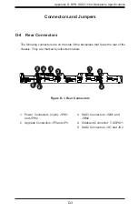
D-5 Rear Connector Definitions
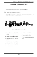
2. Upgrade Connectors
The upgrade connectors are designated JP3
(U6) and JP4 (U7) and are used for manufac-
turers diagnostic purposes only.
Backplane
Main Power
4-Pin Connector
Pin# Definition
1
+12V
2 and 3
Ground
4
+5V
1. Backplane Main Power Connectors
The 4-pin connectors, designated JPW1 and
JPW2 provide power to the backplane. See the
table on the right for pin definitions.
3. SAS Connectors
The SAS connectors are used to connect the
SAS drive cables and are designated JSM1
and JSM2.
4. Sideband Connector
This is the sideband connector for SAS2 and
is designated T-SGPIO1.
5. SAS2 Connectors
The SAS2 connectors are designated JS1
(SAS2 in #1) and JS2 (SAS2 in #2).
Sideband Definitions
(JSM1 - JSM2)
Pin # Definition
Pin # Definition
A0
SB0
C1
SB4
B2
SB1
D1
SB5
C2
SB2
D2
SB6
B1
SB3
A1
SB7
Содержание SC116 Series
Страница 8: ...SC116 Chassis Manual viii Notes...
Страница 42: ...SC116 Chassis Manual 4 6 Notes...
Страница 53: ...5 11 Chapter 5 Chassis Setup and Maintenance Figure 5 11 WIO and UIO Riser Cards UIO Riser Card WIO Riser Card...
Страница 60: ...SC116 Chassis Manual 5 18 Notes...
Страница 70: ...SC116 Chassis Manual 6 10 Notes...
Страница 95: ...E 7 Appendix E BPN SAS3 116A N2 Backplane Specifications Notes...


