75
Appendix D: JBOD Control Board
General Safety Guidelines
•
Always disconnect power cables before installing or removing any components from the
computer, including the control board.
•
Disconnect the power cable before installing or removing any cables from the control board.
•
Make sure that the control board is securely and properly installed in the chassis to prevent
damage to the system due to power shortage.
D.3 Components, Connectors, and Jumpers
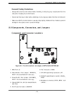
Component and Connector Locations
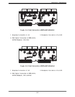
Figure D-1. Front Connectors & Jumpers of BPN-SAS3-947HCB-JB
1. IPMI Port: J2.
2. Reset Button Test Jumper: JRSTBTN_
TEST1 (for manufacturer's use only).
3. Power Button Test Jumper: JPWRBTN_
TEST1 (for manufacturer's use only).
4. Debug COM Port: JP2 (for manufacturer's
use only).
5. Fan Power Connector: JFANPW1.
6. Fan Connector: JFAN1.
7. CPLD Programming Connector: JP1.
8. HUBA Programming Connector: JHUBA_
PRG1.
9. Midplane Connectors: BCN1, BCN2, and
JMCN1.
1
9
9
9
5
6
7
8
4
2
3


